X-ray imaging system convenient to adjust physical alignment of components

A technology of various components and optical imaging, applied in the field of X-ray applications, can solve the problems of inflexible position and attitude adjustment methods, low intelligence and automation, and low coupling degree, so that it is suitable for popularization and use, and avoids cumbersome use , to avoid the effect of radiation

Active Publication Date: 2019-10-08
晓智未来(成都)科技有限公司
View PDF16 Cites 0 Cited by
  • Summary
  • Abstract
  • Description
  • Claims
  • Application Information

AI Technical Summary

Problems solved by technology

[0008] The purpose of the present invention is to provide an X-ray imaging system that facilitates the adjustment of the physical alignment of each component; the present invention solves the problem that the coupling degree of the existing X-ray imaging system is too high or too low, and the adjustment method of the position and attitude of the hardware is not flexible enough, Problems such as ease of use, intelligence and low degree of automation; the distance from the ray source end to the ray receiving end in the present invention can be continuously changed, the spatial position can be adjusted, and the angle at which the X-rays emitted by the ray source end are incident on the ray receiving end is variable. The invention calculates the center point of the patient's part to be detected, the center point of the ray receiving end, and the center point of the ray source end by acquiring the natural light image, and then combines the angle of the ray source end (that is, the plane normal vector of the ray source end and the plane normal vector of the ray receiving end The included angle), the distance from the ray source end to the surface of the object in space, to achieve the purpose of adjusting the physical alignment of each part of the X-ray imaging system

Method used


Image

  • X-ray imaging system convenient to adjust physical alignment of components
  • X-ray imaging system convenient to adjust physical alignment of components
  • X-ray imaging system convenient to adjust physical alignment of components

Examples


Embodiment 1

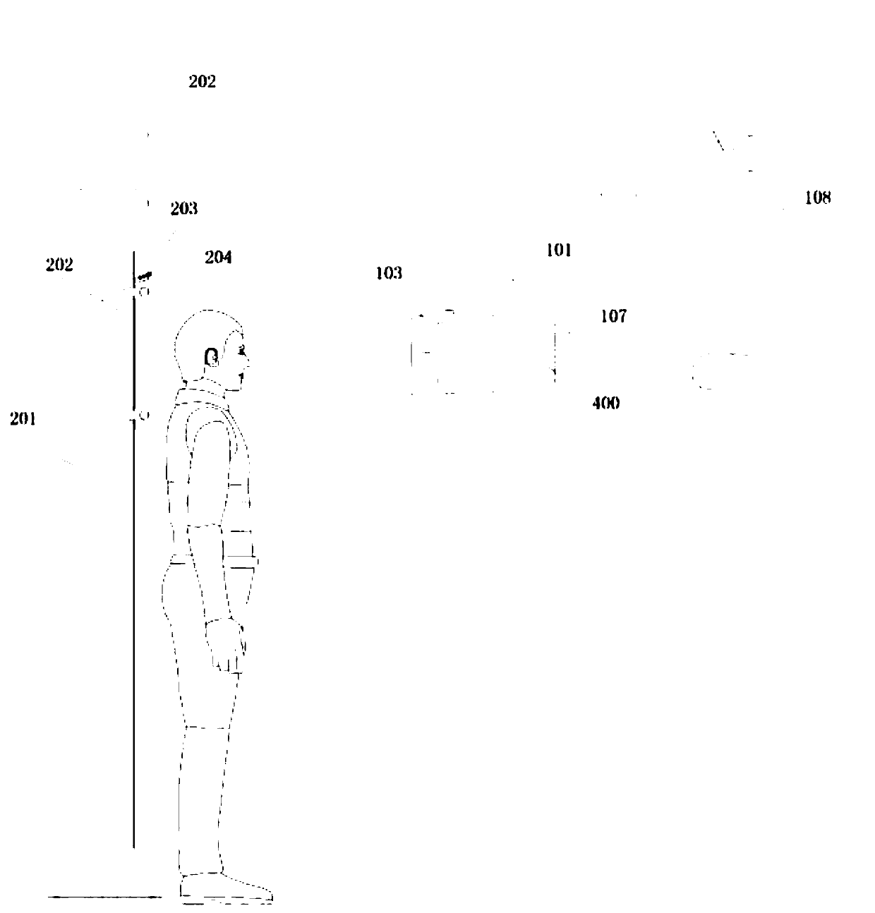
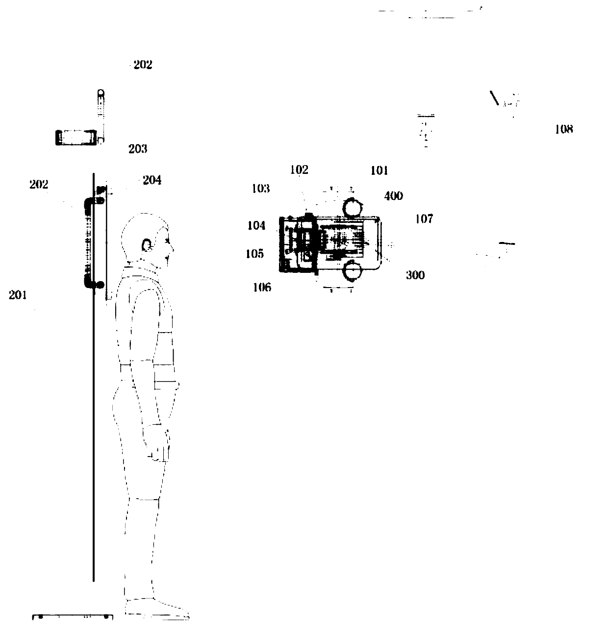
[0049] Such as Figure 1-2 As shown, an X-ray imaging system that is convenient for adjusting the physical alignment of each component includes a ray source end, a ray receiving end, a universal adjustment mechanism and a column adjustment mechanism, and also includes a ray source end, a ray receiving end, and a universal adjustment mechanism. The control module for the communication connection between the mechanism and the column adjustment mechanism;

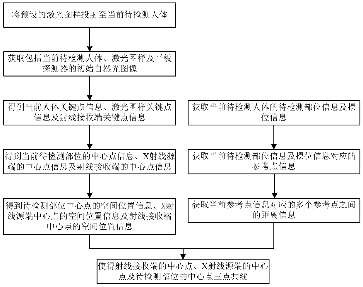
[0050] The ray source end is used to obtain natural light images, distance information and angle information, and to emit X-ray and laser patterns;

[0051] The ray receiving end is used to receive the X-ray emitted by the ray source end and output the X-ray image;

[0052] The universal adjustment mechanism is used to adjust the spatial position of the ray source end, and adjust the angle between the X-ray emitted by the ray source end and the ray receiving end;

[0053] Column adjustment mechanism, used to adjust the heigh...

Embodiment 2

[0057] This embodiment is a further improvement made on the basis of Embodiment 1. The difference between this embodiment and Embodiment 1 is:

[0058] In this embodiment, the X-ray imaging system described in the embodiment to facilitate the adjustment of the physical alignment of each component also includes a display terminal connected to the control module in communication; the display terminal is used to display natural light images, distance information, angle information, ray receiving terminal Height information, position information of the ray source end and / or angle information of the ray source end.

Embodiment 3

[0060] This embodiment is a further improvement made on the basis of Embodiment 2. The difference between this embodiment and Embodiment 2 is:

[0061] In this embodiment, the ray source end includes a housing, a laser source and an X-ray source that are both embedded in the housing and have the same optical field area, and a laser source that is embedded in the housing and communicates with the control module respectively. Image acquisition device, distance measuring device and angle measurement device; the image acquisition device is used to obtain natural light images, and the distance measurement device is used to obtain distance information between multiple preset reference points; the angle measurement device is used to obtain laser sources and X-rays The operating angle of the source, wherein the operating angle includes a horizontal deflection angle and a vertical pitch angle. By obtaining natural light photos, the angle of the ray source end and the distance from the ...


PUM


Abstract

The invention belongs to the technical field of X ray application and discloses an X-ray imaging system convenient to adjust the physical alignment of components. The X-ray imaging system comprises aray source end, a ray receiving end, an universal adjusting mechanism, a standing column adjusting mechanism and a control module, wherein the control module is in communication connection with the ray source end, the ray receiving end, the universal adjusting mechanism and the standing column adjusting mechanism. The X-ray imaging system has the advantages that the distance between the ray sourceend the ray receiving end can change continuously, the spatial positions of the ray source end the ray receiving end can be adjusted, the incidence angle of the X ray which is emitted by the ray source end and goes into the ray receiving end can be changed, and accordingly physical alignment of the components of the X-ray imaging system can be adjusted; the X-ray imaging system is convenient to use, capable of increasing the quality of X-ray images, capable of preventing human bodies from being exposed to unnecessary radiation and suitable for being popularized and used.

Description

technical field [0001] The invention belongs to the technical field of X-ray applications, and in particular relates to an X-ray imaging system for conveniently adjusting the physical alignment of various components. Background technique [0002] X-ray images can enable doctors to have an intuitive understanding of the structure of tissues and organs in the patient's body. The existing X-ray imaging system consists of three parts, namely the ray source end and its subsidiary components, the ray receiver and its subsidiary components, and other module parts; wherein, the ray source part and the ray receiver part have three parts: Two linkage methods: no linkage at all, the positions of the two parts need to be adjusted separately when taking X-ray images; linkage through physical structures such as brackets, so as to move at the same distance in the same direction; the positions of the ray source end and the ray receiver end are fixed and cannot be changed. [0003] However...

Claims


Application Information

Patent Timeline
Patent Type & Authority Applications(China)
IPC IPC(8): A61B6/00
CPCA61B6/44A61B6/54A61B6/40Y02E10/50
Inventor 何香颖张军孙雨
Owner 晓智未来(成都)科技有限公司
Why Eureka
Try Eureka