Liquid supply valve

A liquid supply and valve stem technology, which is applied in the direction of sliding valves, valve details, valve devices, etc., can solve the problems of unfavorable maintenance and replacement of liquid supply valves, unfavorable use of liquid supply valves, and unfavorable use by users, etc., to achieve a simple structure , Firm fixation, easy installation and disassembly

Active Publication Date: 2019-10-08
ZHEJIANG CHUANGAN HYDRAULIC TECH CO LTD
View PDF5 Cites 2 Cited by
  • Summary
  • Abstract
  • Description
  • Claims
  • Application Information

AI Technical Summary

Problems solved by technology

[0002] The liquid supply valve is installed at the outlet of the refrigerator pump, which can prevent the impact of system pressure shock on the refrigerator pump. In addition, when the refrigerator pump is not working, it can prevent the system oil from flowing back into the oil tank through the refrigerator pump. The liquid supply valve is in use When the control port has control pressure, the oil port is connected, and the oil can flow freely in two directions; the hydraulic cylinder can be locked; it can be used as the support valve of the vertical hydraulic cylinder; it can maintain pressure; the traditional supply When the liquid valve is used, the conduit of the refrigerator pump is directly connected to both sides of the liquid supply valve. This method of connection is troublesome to install and disassemble, time-consuming and laborious, which is not conducive to the user's use, and is not conducive to the user's maintenance and replacement of the liquid supply valve. When impacting, it is very easy to cause the pipe connected to the liquid supply valve to fall off directly, which is not conducive to the use of the liquid supply valve; in view of these defects, it is necessary to design a liquid supply valve

Method used


Image

  • Liquid supply valve
  • Liquid supply valve
  • Liquid supply valve

Examples


Embodiment Construction

[0019] The following will clearly and completely describe the technical solutions in the embodiments of the present invention with reference to the accompanying drawings in the embodiments of the present invention. Obviously, the described embodiments are only some, not all, embodiments of the present invention. Based on the embodiments of the present invention, all other embodiments obtained by persons of ordinary skill in the art without making creative efforts belong to the protection scope of the present invention.

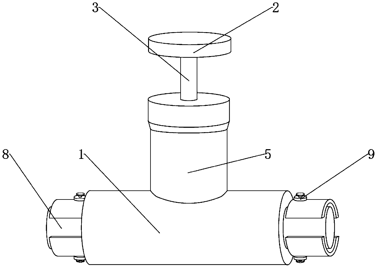
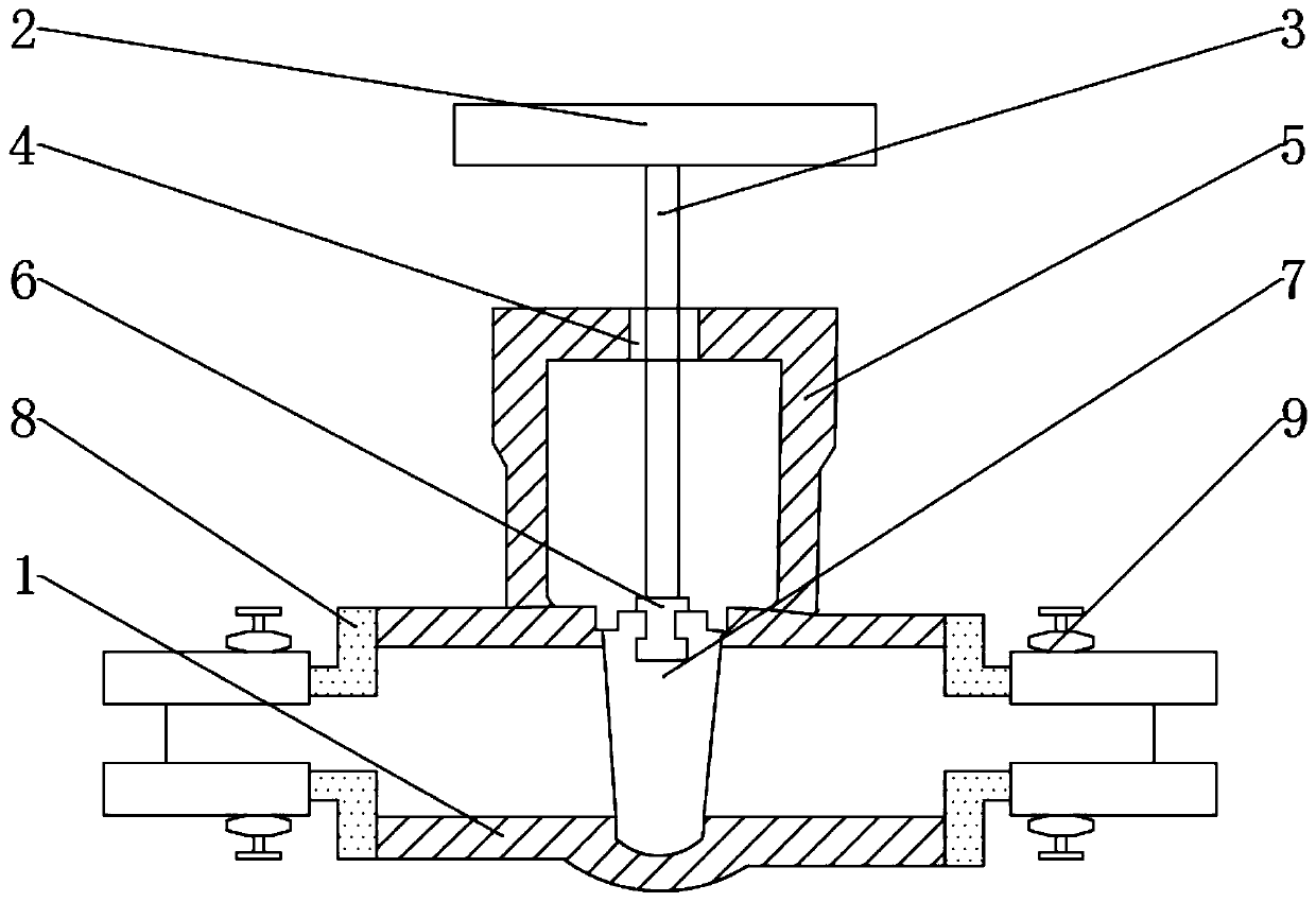
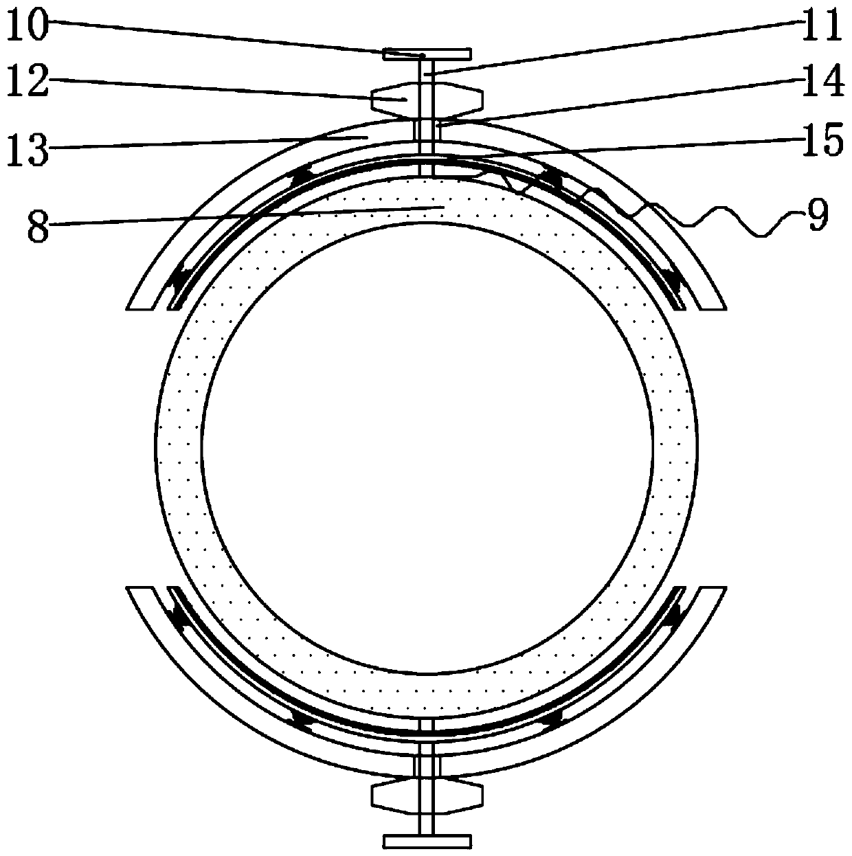
[0020] see Figure 1-5 , the present invention provides a technical solution: a liquid supply valve, including a liquid supply valve seat 1, a valve handle 2, a valve stem 3, a top hole 4, a valve sleeve 5, a valve stem connector 6, a valve core 7, a connecting Sleeve 8 and fixed assembly 9, the valve sleeve 5 is welded on the top of the valve seat 1 of the liquid supply valve, the valve seat 1 of the liquid supply valve is bonded with a plastic pad, and the s...


PUM


Abstract

The invention discloses a liquid supply valve. The liquid supply valve comprises a liquid supply valve seat, a valve handle, a valve rod, a top hole, a valve sleeve, a valve core, connecting sleeves and a fixing component, wherein the top of the liquid supply valve seat is welded with the valve sleeve, the top hole is formed at the top of the valve sleeve, the interior of the top hole is sleeved with the valve rod, the top of the valve rod is welded to the valve handle, and the valve handle is positioned on the top of the valve sleeve; the bottom of the valve rod is sleeved with the valve rodis connected with a valve rod connecting head, the outer side of the valve rod connecting head is sleeved with the valve core, and the valve core is positioned inside the liquid supply valve seat; thetwo sides of the liquid supply valve seat are welded with the connecting sleeves, and the outer sides of the connecting sleeves are welded with threaded rods. The liquid supply valve has the advantages of being simple structure and adopting a clamping mode to fix instead of a traditional mode of fixing through direct sleeving, thus the fixing is firmer, the mounting and dismounting is more convenient, and the maintenance for users and the replacement of the valve is facilitated; in addition, when the valve suffers an external impact, a reset spring can provide elastic force to counteract impact force, thus avoided shaking and even falling of a refrigerator guide pipe arranged at the outer side of the connecting sleeves due to external shaking.

Description

technical field [0001] The invention relates to the technical field of liquid supply valves, in particular to a liquid supply valve. Background technique [0002] The liquid supply valve is installed at the outlet of the refrigerator pump, which can prevent the impact of system pressure shock on the refrigerator pump. In addition, when the refrigerator pump is not working, it can prevent the system oil from flowing back into the oil tank through the refrigerator pump. The liquid supply valve is in use When the control port has control pressure, the oil port is connected, and the oil can flow freely in two directions; the hydraulic cylinder can be locked; it can be used as the support valve of the vertical hydraulic cylinder; it can maintain pressure; the traditional supply When the liquid valve is used, the conduit of the refrigerator pump is directly connected to both sides of the liquid supply valve. This method of connection is troublesome to install and disassemble, time...

Claims


Application Information

Patent Timeline
Patent Type & Authority Applications(China)
IPC IPC(8): F16K3/02F16K3/314F16K27/04F16L21/08
CPCF16K3/02F16K3/314F16K27/04F16L21/08
Inventor 周海钱
Owner ZHEJIANG CHUANGAN HYDRAULIC TECH CO LTD
Why Eureka
Try Eureka