

CNN-Bagging-based fault diagnosis method for UAV bearing
A fault diagnosis and unmanned aerial vehicle technology, which is applied in computer parts, mechanical parts testing, machine/structural parts testing, etc., can solve the problem that the model accuracy is easily affected by the cardinality, the model training efficiency and fault diagnosis accuracy are low, and there is no Considering the correlation of signal faults and other issues to achieve the effect of improving accuracy and generalization ability, which is conducive to real-time performance and fast training speed
- Summary
- Abstract
- Description
- Claims
- Application Information
AI Technical Summary
Problems solved by technology
Method used
Image

Examples
Embodiment
[0049] For the convenience of description, the relevant technical terms appearing in the specific implementation are explained first:
[0050] EMD (Empirical Mode Decomposition): Empirical Mode Decomposition;
[0051] VMD (variational mode decomposition) variational mode decomposition;
[0052] Bagging(bootstrap aggregating): Self-service sampling aggregation;
[0053] CNN: convolutional neural network;
[0054] ANN (Artificial Neutral Network): artificial neural network;
[0055] RNN (Recurrent Neural Networks): recurrent neural network;
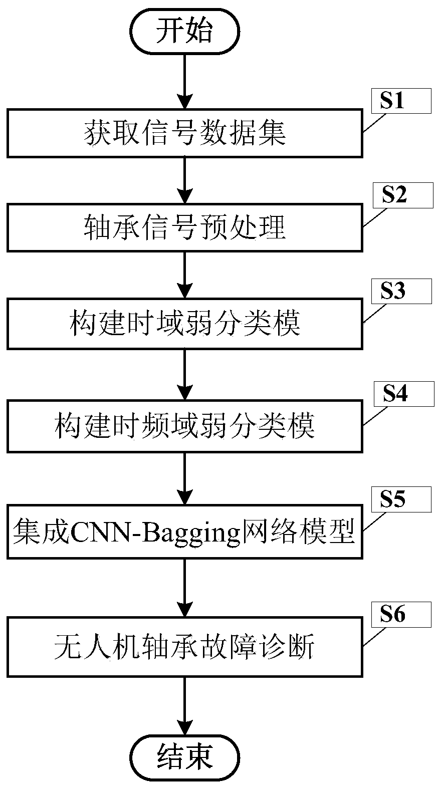
[0056] figure 1 It is a flow chart of the CNN-Bagging-based UAV bearing fault diagnosis method of the present invention.
[0057] In this example, if figure 1 Shown, a kind of unmanned aerial vehicle bearing fault diagnosis method based on CNN-Bagging of the present invention comprises the following steps:
[0058] S1. Obtain signal data set
[0059] Obtain all bearing signals in the UAV to form a signal data set F={f (i) |i∈[1,m]}...
example
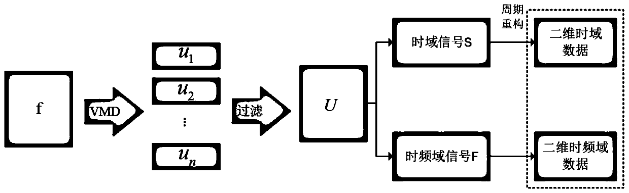
[0097] Suppose a UAV has n bearings, which are f1, f2,..., fn. For f1, the f1 bearing signal is decomposed into time-domain signal S1 and time-frequency signal F1 based on variational mode decomposition (VMD), and then the fault diagnosis of f1 is carried out through the integrated model CNN. Based on the above process, make fault diagnosis for bearings f2...fn respectively, the diagnosis process is as follows Figure 7 As shown, finally judge the fault condition of the bearing according to the diagnosis result of each bearing
[0098] Model evaluation parameters accuracy Acc, precision rate P, recall rate R, F1 and calculation speed and other indicators.
[0099]
[0100]
[0101]
[0102]
[0103] Let S N and F N Represent the number of time-domain models and time-frequency domain models respectively, and the final test results are shown in Table 1.
[0104] index parameter S N
F N
ACC(%) · R(%) F1 20 20 96.251 98.639 94.324 0....
PUM
 Abstract
Description
Claims
Application Information