Woven baler warp knitting machine

A technology of warp knitting machine and straw net, applied in the field of warp knitting machine, can solve the problems such as the unreasonable mechanical structure of the swing shaft of the groove needle bed, bar swing shaft, etc., achieve the simplification of the mechanical structure, simplify the mechanical structure, and increase the speed of the whole machine Effect

Pending Publication Date: 2019-10-11
CHANGZHOU XINHUI NETS
View PDF0 Cites 6 Cited by
  • Summary
  • Abstract
  • Description
  • Claims
  • Application Information

AI Technical Summary

Problems solved by technology

[0007] The present invention aims at the problem that the weft inserting bar does not need to move, and the mechanical structure of the groove needle bed pendulum shaft, the needle core bed pendulum shaft and the bar pendulum shaft is unreasonable, and designs a new structure bale net warp knitting machine

Method used


Image

  • Woven baler warp knitting machine
  • Woven baler warp knitting machine
  • Woven baler warp knitting machine

Examples


Embodiment 1

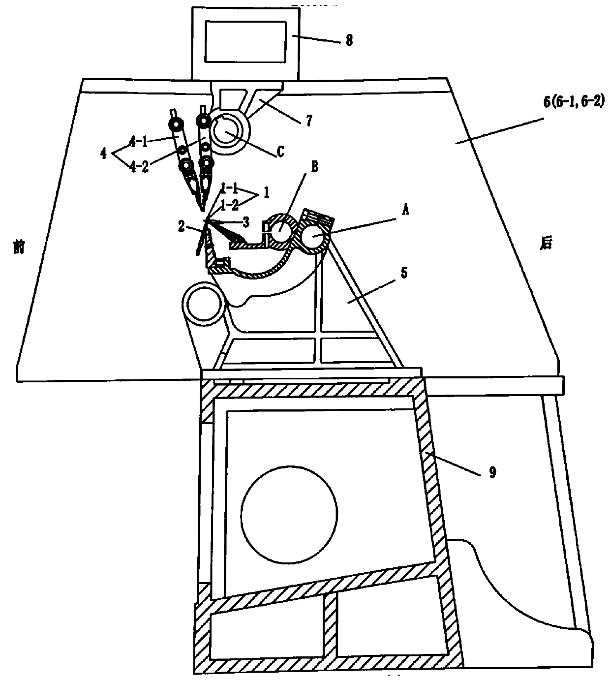
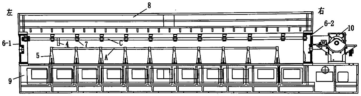
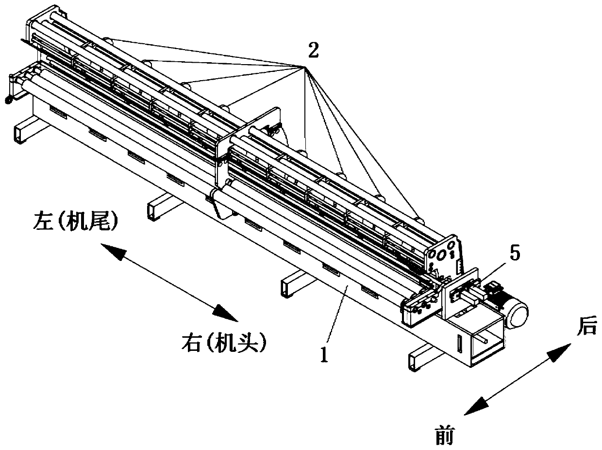
[0036] image 3 , 4 Shown in , 5 is the overall and partial structure of the bale net warp knitting machine, which is composed of an oil tank 1, a wallboard 2, a loop forming device 3, a bar 4, a traverse device 5, and pulling, coiling, and let-off, etc. Among them, the structure of oil tank 1, loop forming device 3, traverse device 5, and pulling, coiling, let-off, etc. is the same as that of commonly used warp knitting machines with few bars, and the structure and movement of wallboard 2 and bars 4 It is different from wall panels and bars in existing warp knitting machines.

[0037]Described wallboard 2 has the hole that supports groove needle pendulum shaft 6, needle core pendulum shaft 7, bar pendulum shaft 8 equiaxes, Image 6 As shown, these holes are all on the overall structure of the wallboard, and the mutual positional relationship between these holes is guaranteed by machining, so as to ensure the balance between the groove needle swing shaft 6, needle core swing...

Embodiment 2

[0053] Figure 8 Shown is another embodiment that the weft insertion bar 4-2 is installed in a fixed position and does not swing.

[0054] 12 is mounting seat, is made up of 12-1 and 12-2 two halves, and 14 is mounting shaft. Mounting shaft 14 is fixedly installed in the hole of wallboard 2 and prohibits motionless. The bolt 13 connects the two halves of the mounting base 12 - 1 and 12 - 2 into a whole, so that it is fixed on the mounting shaft 14 . Bolt 11 (11-1, 11-2) passes through the waist hole of slide bar seat 4-2-1, is tightened in the threaded hole of mounting seat 12, and weft inserting bar 4-2 is fixedly installed in mounting seat 12 superior. Also can have two light holes that pass on the mounting seat 12, bolt 11 passes light hole, utilizes nut and bolt 11 to cooperate and tighten, and weft insertion bar 4-2 is fixedly installed on the mounting seat 12.

[0055] Because mounting base 12 is fixed on the mounting shaft 14, and mounting shaft 14 is fixedly instal...

Embodiment 3

[0059] Figure 9 Shown is another embodiment of the fixed position support to which the weft insertion bar 4-2 is mounted.

[0060] 15 is a hanging seat, which is made up of two halves of 15-1 and 15-2. There are semicircular holes on 15-1 and 15-2, and 15-1 and 15-2 are fixed on the connecting shaft 9 by bolts, as Install the fixing seat of the weft inserting bar. The suspension seat 15 is installed between the parallel wallboards 2, a suspension seat 15 is installed between every two wallboards, and a suspension seat 15 can also be installed between the multi-bar wallboards.

[0061] Threaded hole is arranged on the suspension seat 15, or the light hole of passing through, by bolt 10, weft insertion bar 4-2 is fixed on the suspension seat 15.

[0062] The mechanical structure of the weft-inserting bar of the present invention is the same as that of the existing machine, and the structure of the traversing motion device is different. Since no swing is required, the new stru...


PUM


Abstract

The invention discloses a woven baler warp knitting machine. The machine comprises a wall board, a connecting shaft, a guide bar swing shaft, a slot needle swing shaft, a needle core swing shaft, a chain guide bar, a weft insertion guide bar, a needle core, a knitting needle, a knockover needle and a transverse moving device; the wall board comprises an end wall board body and a middle wall boardbody, the middle wall board body is fixed to a connecting shaft, the two ends of the connecting shaft are fixed to the end wall board, by means of supporting and positioning of the connecting shaft tothe upper portion of the wall board, the guide bar swing shaft, the slot needle swing shaft and the needle core swing shaft are horizontally and transversely installed on the wall board and can rotate relative to the wall board, the chain guide bar and the weft insertion guide bar are mutually independent, and the chain guide bar is installed on the guide bar swing shaft. Accordingly, two movements (reciprocating swing and linear movement) of the weft insertion guide bar on an existing machine are changed into one movement, that is to say, only reciprocating linear transverse movement is performed, and the inertia force and inertia moment of weft insertion guide bar movement are reduced; the mechanical structure of the guide bar part is simplified; the movement precision between knittingelements is improved.

Description

technical field [0001] The invention belongs to the technical field of warp knitting machines, and relates to a novel warp knitting machine for weaving bale nets. Background technique [0002] Bale net is a large mesh (hole) fabric used to bind straw, pasture and other plants, and it is named for its function. Bale net is a kind of warp knitted fabric, also known as no-knotty fishing net, which is generally produced by warp knitting machine. The structural composition of the bale net is that there are multiple groups of parallel and identical warp knitting chains in the longitudinal direction, and there are weft insertions in the horizontal direction, and the weft insertions connect the longitudinal knitting chains to form a mesh fabric. The structural characteristics of the bale net are that the braided wire is relatively thick (high machine size) and the mesh is large. Specifically, the distance between each braided chain in the horizontal direction and the longitudinal (...

Claims


Application Information

Patent Timeline
Patent Type & Authority Applications(China)
IPC IPC(8): D04B27/26D04B27/00D04B27/24
CPCD04B27/00D04B27/24D04B27/26Y02P70/62
Inventor 徐晓辉曹清云徐嘉婕
Owner CHANGZHOU XINHUI NETS
Why Eureka
Try Eureka