
Hydroelectric impeller

An impeller and blade technology, which is applied in the field of impellers of hydropower generation, can solve the problems of increasing installation difficulty, increasing installation difficulty, and higher installation position requirements.

Pending Publication Date: 2019-10-11
XUZHOU UNIV OF TECH
View PDF0 Cites 1 Cited by
  • Summary
  • Abstract
  • Description
  • Claims
  • Application Information

AI Technical Summary

Problems solved by technology

[0003] There are many deficiencies in the hydropower impeller at the present stage: First, the impeller needs to be installed at a position with a large water level drop to effectively ensure the power generation efficiency. The construction cost is relatively high; second, the existing impeller can only adapt to power generation operations in one direction of water flow, so that the installation process must also consider the matching of the direction of water flow with the working direction of the blades, which further increases the difficulty of installation

Method used


Image

  • Hydroelectric impeller

Examples


Embodiment Construction

[0016] The present invention will be further described below.

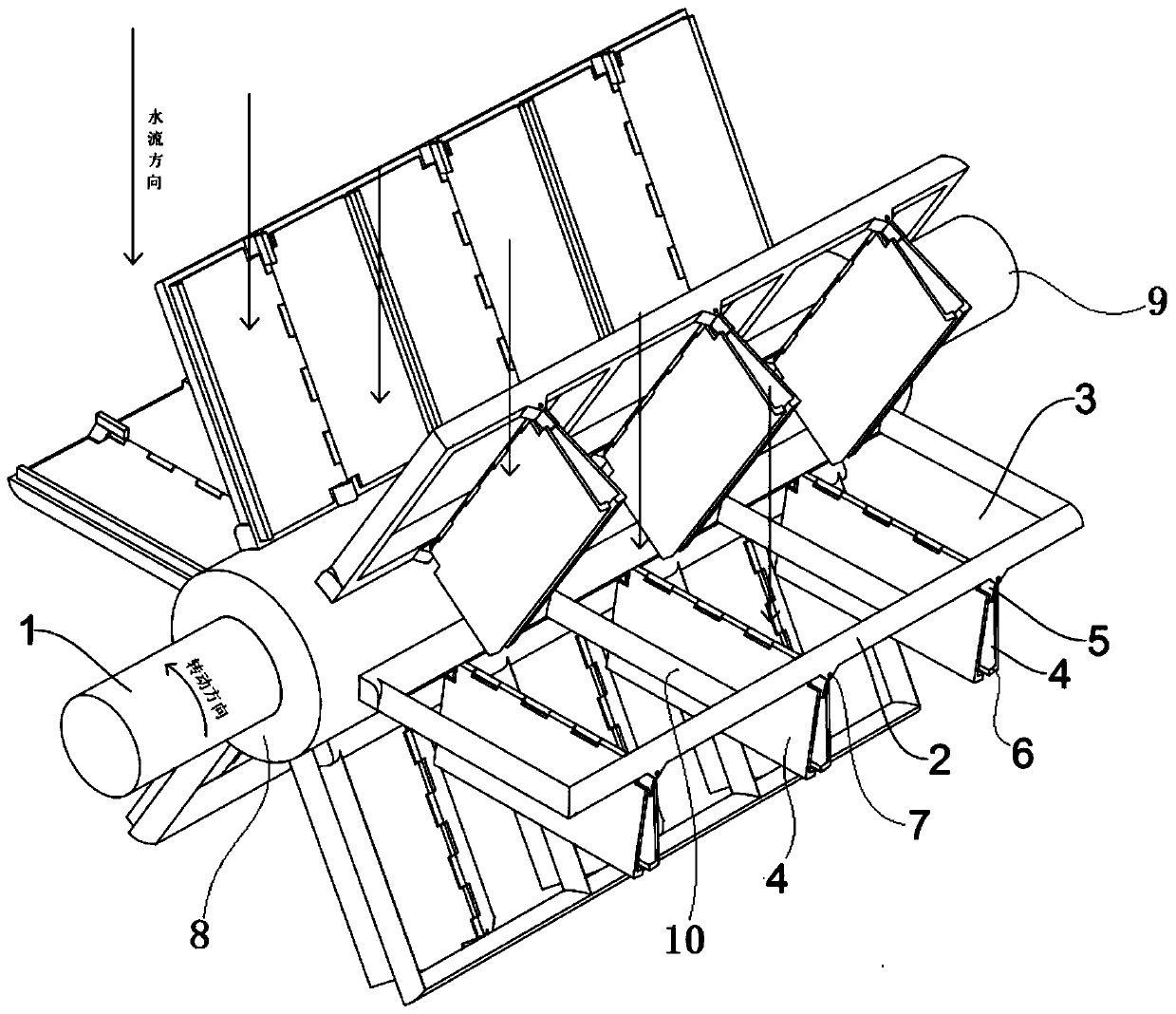
[0017] Such as figure 1 As shown, a hydroelectric impeller includes a rotating body 9, a plurality of blades 4 and a plurality of installation frames 2 uniformly distributed along the circumference of the rotating body 9;

[0018] The length direction of the mounting frame 2 is consistent with the axial direction of the rotating body 9, and its width direction is consistent with the radial direction of the rotating body 9; the mounting frame 2 is fixedly connected with the middle part of the rotating body 9 through a frame on its inner side, The interior of the installation frame 2 is evenly fixed and connected with a plurality of isolation beams 10 extending radially along its length direction;

[0019] A plurality of isolation beams 10 isolate the interior of the installation frame 2 into a plurality of blade unit accommodation spaces 3; each blade unit accommodation space 3 is provided with a blade unit;

[0...


PUM


Abstract

Provided is a hydroelectric impeller. A mounting frame is fixedly connected with the middle portion of a rotating body. A plurality of isolation beams are fixedly connected inside the mounting frame.The isolation beams isolate the interior of the mounting frame into a plurality of blade unit accommodating spaces. A blade unit is arranged in each blade unit accommodating space. Each blade unit iscomposed of a hinge shaft fixedly connected to the middle of the corresponding blade unit accommodating space and two blades located on the same side of the corresponding blade unit accommodating space, each hinge shaft isolates the corresponding blade unit accommodating space into two blade accommodating spaces, every two blades and the two corresponding blade unit accommodating spaces are correspondingly arranged, the connecting ends of every two blades are correspondingly hinged to the corresponding hinge shafts, and the free ends of every two blades are limited by the ends of the blade unit accommodating spaces. A limiting stop is fixedly attached to the end, away from the rotating body, of each hinge shaft. The impeller has low installation requirements, can reduce the construction cost of hydroelectric power generation and can adapt to changes in the direction of water flow, and the hydroelectric impeller can be more conveniently installed.

Description

technical field [0001] The invention belongs to the technical field of hydroelectric power generation equipment, in particular to an impeller for hydropower generation. Background technique [0002] In our country, hydropower resources are quite sufficient, and hydropower is clean energy, so our country attaches great importance to hydropower. The basic principle of hydroelectric power generation is to use the water level drop to cooperate with the hydroelectric generator to generate electricity, that is, to use the potential energy of water to convert the mechanical energy of the waterwheel, and then use the mechanical energy to drive the generator to obtain electricity. [0003] There are many deficiencies in the hydropower impeller at the present stage: First, the impeller needs to be installed at a position with a large water level drop to effectively ensure the power generation efficiency. The construction cost is relatively high; secondly, the existing impeller can on...

Claims


Application Information

Patent Timeline
IPC IPC(8): F03B3/12
CPCF03B3/12F03B3/121F03B3/128Y02E10/20
Inventor 李文义胡峰孙言
Owner XUZHOU UNIV OF TECH
Learn More