High thermal conductivity geothermal energy heat exchange tunnel system and its construction method

A technology with high thermal conductivity and geothermal energy, applied in heat exchange equipment, tunnels, geothermal energy, etc., can solve the problems of increasing construction difficulty, high requirements for water pumps, and affecting tunnel water stop, so as to improve the problem of linear heat sources and reduce the Uniform temperature difference stress and deformation, strong engineering applicability

Active Publication Date: 2021-03-16
NINGBO UNIVERSITY OF TECHNOLOGY
View PDF10 Cites 0 Cited by
  • Summary
  • Abstract
  • Description
  • Claims
  • Application Information

AI Technical Summary

Problems solved by technology

However, the heat-conducting liquid has great resistance to penetrate the water-permeable material under the action of pressure, which requires high requirements for water pumps; the heat exchange layer has high requirements for the compactness and porosity of on-site paving and compaction, which increases the difficulty of construction; and This construction method is relatively cumbersome to operate and affects the construction period. To a certain extent, it will affect the tunnel water-stop problem.
In addition, most of the current energy tunnel technology focuses on using geothermal energy for antifreeze heating, ignoring its function of storing heat energy and cooling buildings in the tunnel and nearby buildings, which weakens the functionality and has certain limitations

Method used


Image

  • High thermal conductivity geothermal energy heat exchange tunnel system and its construction method
  • High thermal conductivity geothermal energy heat exchange tunnel system and its construction method
  • High thermal conductivity geothermal energy heat exchange tunnel system and its construction method

Examples


Embodiment Construction

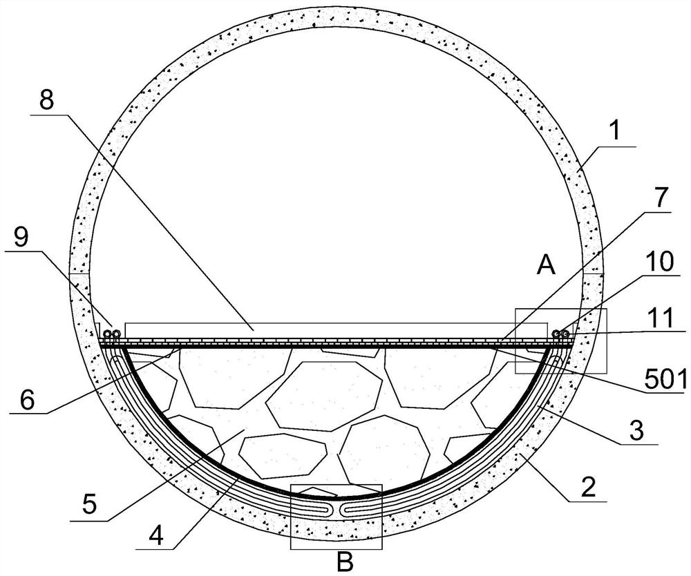
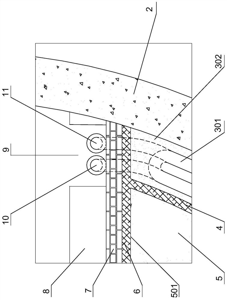
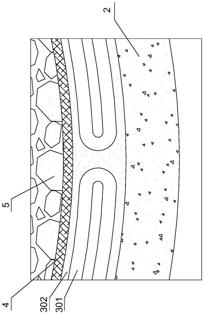
[0045] Examples, see Figure 1 to Figure 4 Shown: the high thermal conductivity geothermal energy heat exchange tunnel system, including the upper tunnel lining 1 and the lower tunnel inverted arch 2 that cooperate with each other. That is, viewed in cross-section, the second tunnel lining 1 and the tunnel invert 2 form a closed ring.

[0046] Further speaking:

[0047]A patch type prefabricated geotextile bag heat exchange layer 3 is laid on the upper surface of the tunnel invert 2 . The patch-type prefabricated geotextile bag heat exchange layer 3 includes a geotextile bag (not shown in the figure), a heat exchange tube 301 and a high thermal conductivity filler 302 located in the geotextile bag. Among them, the length of the geotextile bag is prefabricated according to the design requirements; comprehensively considering the convenience of on-site construction, the heat exchange tube 301 can be arranged in full width or half width, and the heat exchange tube 301 can be ar...


PUM

PropertyMeasurementUnit
particle diameteraaaaaaaaaa
voidageaaaaaaaaaa

Abstract

The invention discloses a high-heat-conductivity ground temperature energy heat exchange tunnel system. The system comprises a tunnel second lining located on the upper portion and a tunnel inverted arch located on the lower portion, wherein the tunnel second lining and the tunnel inverted arch cooperate with each other. A patch type prefabricated geotechnical cloth bag heat exchange layer is paved on the upper surface of the tunnel inverted arch and comprises a geotechnical cloth bag, a heat exchange pipe and high-heat-conductivity filler, wherein the heat exchange pipe and the high-heat-conductivity filler are located in the geotechnical cloth bag. A lower waterproof layer is paved on the patch type prefabricated geotechnical cloth bag heat exchange layer. A phase change energy storage layer is arranged on the lower waterproof layer in a filling manner. A spread-out face is formed on the upper surface of the phase change energy storage layer. An upper waterproof layer is paved on theupper portion of the spread-out face. A heat insulation layer is arranged on the upper waterproof layer. A pavement layer located in the middle and a water pipe trench located on the side are arranged on the upper portion of the heat insulation layer. A water supply pipe and a water return pipe are arranged in the water pipe trench. The water supply pipe communicates with a water inlet of the heat exchange pipe, and the water return pipe communicates with a water outlet of the heat exchange pipe. The system has the advantages of being simple in operation, high in engineering applicability andlow in heat storage heat response.

Description

technical field [0001] The invention relates to the technical field of energy utilization, in particular to a high thermal conductivity geothermal energy heat exchange tunnel system. The invention also relates to the construction method of the high thermal conductivity geothermal energy heat exchange tunnel system. Background technique [0002] The energy tunnel technology combines the ground source heat pump system with the lining structure of the tunnel engineering, and utilizes the shallow geothermal energy in the surrounding rock of the tunnel or the surrounding soil to heat or cool the buildings in the tunnel and nearby. Low-cost new technology. [0003] Usually, during the construction of energy tunnels, the heat exchange tubes are buried between the primary support of the tunnel and the secondary lining, or embedded in the shield segment, and the surrounding rock or soil layer of the tunnel is used as the heat exchange layer. For example, the Chinese invention paten...

Claims


Application Information

Patent Timeline
Patent Type & Authority Patents(China)
IPC IPC(8): F25B30/06F24T10/15F28D20/02F28F21/00F28F21/04E21D11/38
CPCE21D11/38F25B30/06F28D20/021F28F21/00F28F21/045F24T10/15Y02E10/10Y02E60/14
Inventor 陈斌吕志祥孔纲强
Owner NINGBO UNIVERSITY OF TECHNOLOGY
Why Eureka
Try Eureka