
Coding circuit and coding method of active capacitance pen

A capacitive stylus, active technology, applied in electrical digital data processing, data processing input/output process, instruments, etc., can solve the problem that the coding amplitude is not high enough, the capacitor has not been discharged and recharged, and the reliability cannot be guaranteed. , to achieve the effect of increasing the coding range, reducing power consumption, reducing disconnection and even occasionally unable to write

Pending Publication Date: 2019-10-11
MAXEYE SMART TECH CO LTD
View PDF1 Cites 11 Cited by
  • Summary
  • Abstract
  • Description
  • Claims
  • Application Information

AI Technical Summary

Problems solved by technology

Chinese patent 201780002200.2 discloses a signal generating circuit and coding method. Although it can reduce power consumption a little, it is very difficult to implement the solution, and the range of coding is not high enough
The pen holder of an active capacitive pen is generally in contact with the ground of the main board through a POGOPIN or a spring. Generally, it is a single point of contact. To make contact with 4 POGOPINs in a pen holder, not only the cost is increased, but also the reliability is impossible. Guaranteed
This practice will cause the pen to have a very high possibility of power failure during the writing process.
Moreover, the amplitude of the overall circuit output is related to the charging and discharging of the capacitor, because charging and discharging sometimes in the process of fast time switching may easily lead to the situation that the capacitor is not fully discharged and recharged, resulting in poor consistency of subsequent production products, which will affect users. experience

Method used


Image

  • Coding circuit and coding method of active capacitance pen
  • Coding circuit and coding method of active capacitance pen
  • Coding circuit and coding method of active capacitance pen

Examples


Embodiment Construction

[0030] The preferred embodiments of the present invention will be further described in detail below.

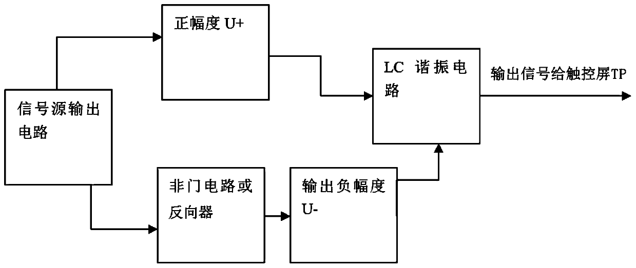
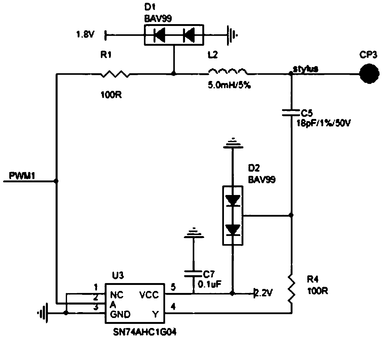
[0031] Such as figure 1 As shown, a coding circuit of an active capacitive pen, which includes a signal source output circuit, an LC resonant circuit, a NOT gate circuit or an inverter and a signal spring, the signal source output circuit outputs a positive amplitude U+ signal and the LC resonant circuit connected, and at the same time, the signal source output circuit outputs a negative amplitude U-signal through a NOT gate circuit or an inverter, and is connected to the LC resonant circuit, and the LC resonant circuit is connected to the signal spring of the active capacitor pen. The absolute value of the signal amplitude of the positive amplitude U+ signal is the same as that of the output negative amplitude U− signal. The distance between the center of the signal spring and the edge of the PCB is greater than three times the radius of the signal spring.

[0032] Specifi...


PUM


Abstract

The invention provides a coding circuit and a coding method of an active capacitance pen. The coding circuit comprises a signal source output circuit, an LC resonance circuit, a NOT gate circuit or inverter and a signal spring. The signal source output circuit outputs a positive amplitude U + signal to the LC resonance circuit. At the same time, the signal source output circuit outputs a negativeamplitude U-signal to the LC resonant circuit through a NOT circuit or an inverter. The LC resonance circuit is connected with a signal spring of the active capacitance pen. By adopting the technicalscheme, the power consumption of the active pen can be reduced under the condition of improving the coding amplitude, the circuit structure is simple, the implementation is convenient, the reliabilityis high, and the conditions of disconnection and even occasional incapability of writing during writing are greatly reduced; and the consistency of products in the production process is easy to control, and the cost is low.

Description

technical field [0001] The invention belongs to the field of touch technology, and in particular relates to a coding circuit and a coding method of an active capacitive pen. Background technique [0002] With the development of science and technology, most screens currently use capacitive touch screens. Capacitive touch screens are divided into those that do not support touch capacitive pens and those that support touch capacitive pens. Especially in recent years, capacitive screens with stylus are used in education, financial industry, and design, so the writing performance and power consumption of active capacitive pens on capacitive touch screens have become more concerned issues. [0003] How an active capacitive stylus can ensure continuous writing on the touch screen and low power consumption has become a technical problem that developers need to overcome. The impedance of the touch screen is different from left to right or from top to bottom, so the coding output sig...

Claims


Application Information

Patent Timeline
Patent Type & Authority Applications(China)
IPC IPC(8): G06F3/0354G06F3/038G06F3/044
CPCG06F3/03545G06F3/0383G06F3/044
Inventor 钟洪耀邓建詹梓煜
Owner MAXEYE SMART TECH CO LTD
Learn More