Bus system and standby bus connecting device

A technology for a backup busbar and a connecting device, which is applied in the field of power systems, can solve the problem of high production cost of power station equipment, and achieve the effects of simple structure, ensuring stability and reducing workload.

Active Publication Date: 2019-10-11
HENAN PINGGAO ELECTRIC +2
View PDF4 Cites 4 Cited by
  • Summary
  • Abstract
  • Description
  • Claims
  • Application Information

AI Technical Summary

Problems solved by technology

[0005] The purpose of the present invention is to propose a spare bus connection device, which can solve the problem of high production cost of power station equipment in the prior art; another purpose of the present invention is to provide a bus system using the spare bus connection device, which is convenient for adjustment, It also has the advantages of low cost and good economy

Method used


Image

  • Bus system and standby bus connecting device
  • Bus system and standby bus connecting device
  • Bus system and standby bus connecting device

Examples


Embodiment Construction

[0046] The specific implementations of the backup bus connection device and the bus system in the present invention will now be described in conjunction with the accompanying drawings.

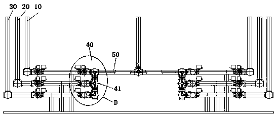
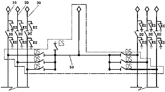
[0047] Such as figure 1 and figure 2 As shown, it is an embodiment of the busbar system in the present invention: the busbar system includes three-phase separately arranged A-phase branch busbar 10, B-phase branch busbar 20 and C-phase branch busbar 30, and also includes the three-phase branch busbar. Each corresponds to the spare bus 50 that acts as a substitute. When a branch bus of a certain phase in the bus system cannot work due to a fault, the operator can make the corresponding spare bus 50 replace the faulty bus by operating the corresponding switch, so that the bus The system can still continue to work stably.

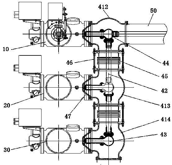
[0048] A-phase branch busbar 10, B-phase branch busbar 20 and C-phase branch busbar 30 all include a busbar barrel and a conductive rod 42 arranged in the busbar barrel. Th...


PUM


Abstract

The invention relates to the technical field of electric power systems, provides a bus system and a standby bus connecting device, and can solve the problem of high production cost of power station equipment in the prior art. The standby bus connecting device comprises a collecting and connecting barrel body, wherein the collecting and connecting barrel body is formed by combining branch barrel bodies which are connected by branch buses of all the phases; branch bus connecting ends used for being connected with branch buses of the corresponding phase, and the branch barrel body connecting endsconnected with the adjacent branch barrel bodies are arranged on each branch barrel body; a standby bus connecting end connected with the standby bus is arranged on one of the branch barrel bodies; the standby bus connecting device further comprises a conducting rod arranged in the collecting and connecting barrel body, and the conducting rod is used for conducting the connecting end of each branch bus and the connecting end of the standby bus; the standby bus connecting end and the branch bus connecting end are both rigid connecting ends, and are used for direct connection of bus barrels ofthe corresponding branch buses and the standby buses; and the two adjacent branch barrel bodies are connected by a flexible connecting end formed by corrugated pipes.

Description

technical field [0001] The invention relates to the technical field of power systems, in particular to a busbar system and a spare busbar connection device thereof. Background technique [0002] In the high-voltage power station transmission system, the three-phase main transformer and the three-phase main bus are respectively provided with a three-phase bus and a gas-insulated metal-enclosed switchgear. If one of the three-phase main transformers bulges, then The entire main transformer needs to be shut down until the fault is repaired before it can be put into operation again. The power outage time of the entire power station is long, and the operation reliability of the power station system is low. [0003] In order to solve the problem of long power outage time and low reliability of the power station, operators in the prior art will use an auxiliary busbar in the power station, such as the patent application document with the application publication number CN106712013A ...

Claims


Application Information

Patent Timeline
Patent Type & Authority Applications(China)
IPC IPC(8): H02J9/02
CPCH02J9/02Y02B70/30Y04S20/20
Inventor 刘超峰陈英张润杰庞永鹏刘恩歌赵恒董清华赵海洋马延柯吴运泽王晓磊包伟
Owner HENAN PINGGAO ELECTRIC
Why Eureka
Try Eureka