
Rapid negative voltage switching circuit

A switching circuit and negative voltage technology, applied in electrical components, transmission systems, etc., can solve the problem that the switching speed cannot meet the high-speed requirements of the phased array antenna system, and achieve the effects of low cost, fast switching speed and fast response.

Pending Publication Date: 2019-10-11
CHENGDU T-RAY TECH CO LTD
View PDF0 Cites 2 Cited by
  • Summary
  • Abstract
  • Description
  • Claims
  • Application Information

AI Technical Summary

Problems solved by technology

[0004] This application provides a fast negative voltage switching circuit to solve the technical problem in the prior art that the switching speed of the signal channel disconnection control of the radio frequency chip cannot meet the high-speed requirements of the phased array antenna system

Method used


Image

  • Rapid negative voltage switching circuit
  • Rapid negative voltage switching circuit

Examples


Embodiment 1

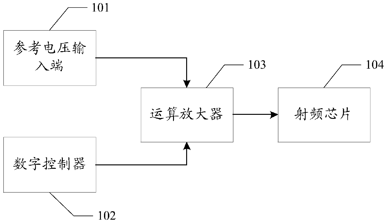
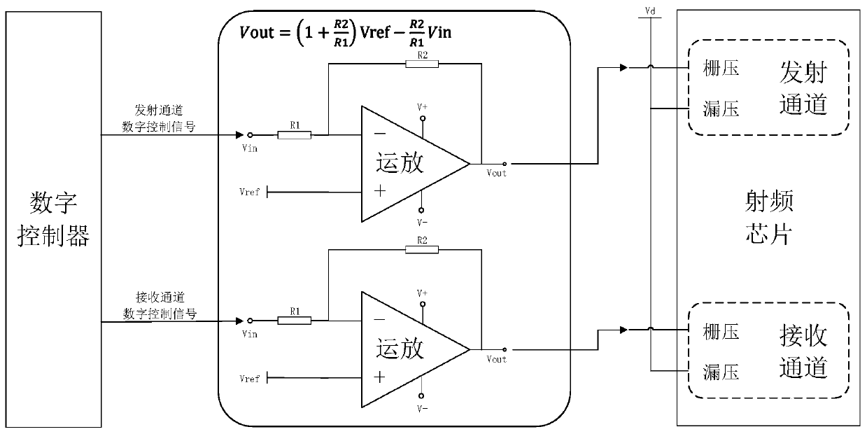
[0032] Please refer to figure 1 , figure 2 , Embodiment 1 of the present application provides a fast negative voltage switching circuit, including:

[0033] The reference voltage input terminal 101 is used to output a predetermined level value V ref the reference voltage;

[0034] The digital controller 102 is used to output a preset level value V in digital control signal;

[0035] The operational amplifier 103 is connected to the reference voltage input terminal and the digital controller respectively, and is used to reversely amplify the numerical control signal based on the reference voltage to generate ref and V in Corresponding negative voltage signal;

[0036] The radio frequency chip 104 includes a signal receiving channel or a signal transmitting channel, and the grid voltage receiving end of the signal receiving channel or the signal transmitting channel is connected to the operational amplifier, so as to receive the negative voltage based on the grid voltage ...


PUM


Abstract

The invention discloses a rapid negative voltage switching circuit. A reference voltage input end for outputting reference voltage with a preset level value Vref is arranged. A digital controller is used for outputting a numerical control signal with a preset level value Vin. A reference voltage input end and the digital controller are connected with an operational amplifier. Therefore, the operational amplifier can be adopted to perform reverse amplification processing on the numerical control signal based on the reference voltage to generate different negative voltage signals, and meanwhile,the different negative voltage signals are output to a gate voltage receiving end of a radio frequency chip to realize opening and closing control on a receiving channel and / or a transmitting channel. By changing the level value of the reference voltage, negative voltages with different voltage values can be output, control over different radio frequency chips is achieved, and therefore the technical scheme has the technical effect of expanding the application range of the negative voltage switching circuit. Meanwhile, due to the fact that the operational amplifier is quick in response and low in cost, the technical effects of high switching speed, high operation efficiency and the like are achieved.

Description

technical field [0001] The invention relates to the technical field of phased array antenna radio frequency chip control, in particular to a fast negative voltage switching circuit. Background technique [0002] At present, when the active phased array antenna is working, it is necessary to quickly switch the transceiver state of the radio frequency chip at the nanosecond level. The existing active phased array antenna transceiver switching control scheme mainly has the following two methods: the first It adopts the method of leakage voltage switching. This method controls the opening or closing of the receiving / transmitting channel of the chip by controlling the voltage on the drain of the chip. This method has the disadvantages of low precision of chip mode switching control, large noise, It is easy to cause chip failure, poor reliability and other shortcomings; the second is to use the gate voltage switching method, which is to control the pinch-off of the corresponding c...

Claims


Application Information

Patent Timeline
Patent Type & Authority Applications(China)
IPC IPC(8): H04B1/44H04B1/401
CPCH04B1/44H04B1/401
Inventor 姚付良伍泓屹胡洋陈建波彭希浩蒋敏
Owner CHENGDU T-RAY TECH CO LTD
Learn More