Infusion system using automatic flow resisting valve as main body

A valve body and main body technology, which is applied in the field of infusion systems, can solve the problems of large space occupation and achieve the effects of small space occupation, easy manufacture and simple structure

Pending Publication Date: 2019-10-15
巨翊科瑞医疗技术(上海)有限公司
View PDF7 Cites 2 Cited by
  • Summary
  • Abstract
  • Description
  • Claims
  • Application Information

AI Technical Summary

Problems solved by technology

However, the infusion tube is located between the valve core and the valve seat, occupying a large space

Method used


Image

  • Infusion system using automatic flow resisting valve as main body
  • Infusion system using automatic flow resisting valve as main body
  • Infusion system using automatic flow resisting valve as main body

Examples


Embodiment 1

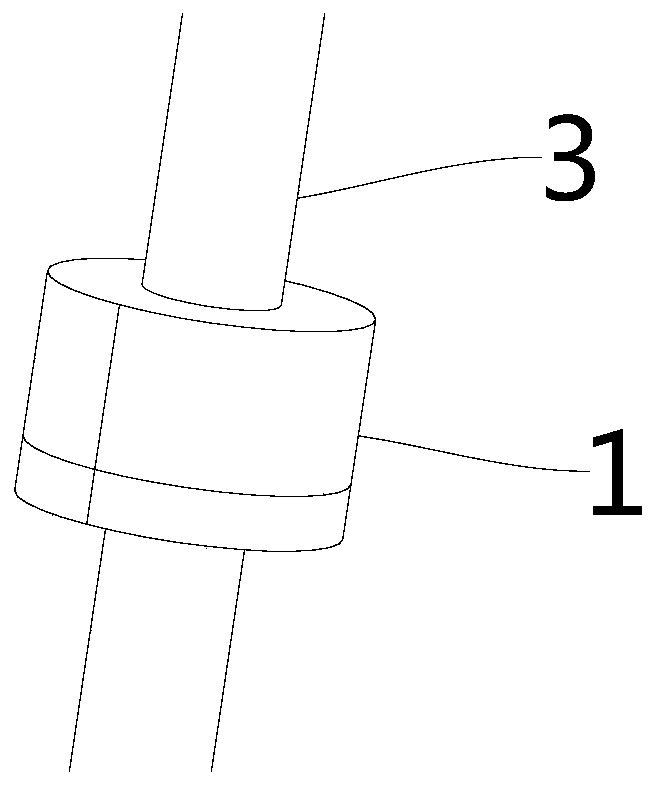
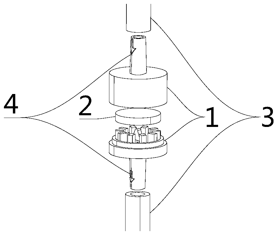
[0031] Such as Figure 1-5 Shown is an infusion system with an anti-flow valve as the main body, including an infusion pump and an infusion tube 3, and an anti-flow valve, which can be set at any position of the infusion tube. The anti-self-flow valve provides an initial pressure, so that the anti-self-flow valve is in a normally closed state that blocks the infusion of the infusion tube. Only when the infusion pump is working normally, the pressure provided by the infusion pump overcomes the initial pressure, so that the anti-self-flow valve is in the infusion tube. The open state of the infusion. Among them, the anti-free flow valve includes a valve body 1 and a valve core 2. The valve body 1 includes a valve body cavity, the valve body 1 is arranged between the infusion tube 3, the upper and lower end surfaces of the valve body 1 are respectively communicated with the infusion tube 3, and the liquid can circulate in the valve body 1. The valve core 2 is arranged in the inne...

Embodiment 2

[0033] Such as Figure 2-5 As shown, the valve body 1 is cylindrical, the inner cavity of the valve body is cylindrical, and the valve core 2 is disc-shaped. The diameter of the valve core 2 is smaller than the diameter of the inner cavity of the valve body. The axis of the valve core 2 coincides with the axis of the valve body 1. A boss 6 extends in the radial direction and then along the axis of the valve core 2 around the liquid inlet at the liquid inlet end of the valve body cavity. Between the boss 6 and the valve core 2 is formed a liquid inlet isolated from the valve body cavity. The chamber 7, the boss 6 and the valve body 1 are integrally formed, and the valve core 2 is made of silicone material with certain elasticity. Further, the cross section of the boss 6 is ring-shaped and forms a cylindrical liquid inlet chamber 7 with the valve core 2. The end surface of the boss 6 close to the valve core 2 is set as a curved surface, so that the contact mode of the boss 6 a...

Embodiment 3

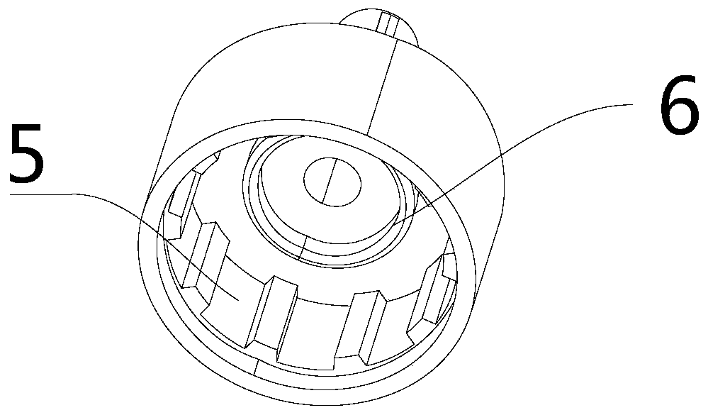
[0035] Such as image 3 As shown, the difference between this embodiment and Embodiment 2 is that the diameter of the valve core 2 in this embodiment is equal to the diameter of the inner cavity of the valve body, so that the liquid medicine is blocked by the valve core 2 and cannot be conducted. Therefore, it is necessary to provide a groove 5 on the side surface of the valve body cavity to allow the liquid medicine to flow to the valve body cavity through the groove 5. Further, the cross section of the groove 5 is a trapezoid, and a plurality of grooves 5 are evenly arranged along the circumferential direction of the side surface of the inner cavity of the valve body.


PUM


Abstract

The invention discloses an infusion system using an automatic flow resisting valve as a main body, and relates to the technical field of medical apparatuses. The infusion system comprises an infusionpump, infusion pipes, and the automatic flow resisting valve arranged at any position of the infusion pipes, wherein the automatic flow resisting valve is used for providing initial pressure, so thatthe automatic flow resisting valve is under a normal off condition of blocking the infusion of the infusion pipes; only when the infusion pump normally works, pressure provided by the infusion pump overcomes the initial pressure, so that the automatic flow resisting valve is under an opening condition where the infusion pipes can perform infusion; the automatic flow resisting valve comprises a valve body and a valve core; the valve body comprises a valve body inner cavity; the valve body inner cavity is formed between the infusion pipes, and communicates with the infusion pipes; the valve coreis arranged in the valve body inner cavity; and the valve body is used for providing the initial pressure to the valve core, so that the infusion pipes are under the normal off condition. The infusion system disclosed by the invention can automatically stop infusion; in the using process, a manual operation factor is removed, the possibility of operation faults is eliminated, and the problem of automatic flowing of the infusion pump can be effectively solved; and the infusion system is in one-way conduction, so that reverse flow of blood is effectively avoided.

Description

Technical field [0001] The present invention relates to the technical field of medical devices, in particular to an infusion system with a self-flow prevention valve as the main body. Background technique [0002] The infusion pump is usually a mechanical or electronic control device, which achieves the purpose of controlling the infusion speed by acting on the infusion catheter. It is often used in situations that require strict control of the amount of infusion and the amount of medicine, such as in the application of blood pressure drugs, antiarrhythmic drugs, intravenous infusion of infants and young children or intravenous anesthesia. [0003] The output end of the infusion pump is provided with a liquid stop device, which functions to prevent the internal liquid flow of the infusion pump, prevent the self-flow problem that may occur in the infusion tube, and ensure the safety of the infusion. The current general technology is to set a liquid stop clamp at the output end, whi...

Claims


Application Information

Patent Timeline
Patent Type & Authority Applications(China)
IPC IPC(8): A61M5/142A61M5/168
CPCA61M5/142A61M5/16881
Inventor 王鸿儒
Owner 巨翊科瑞医疗技术(上海)有限公司
Why Eureka
Try Eureka