Anti-floating system and construction method of sandbar sewage pipe, well

A technology for sewage pipes and sandbars, applied in infrastructure engineering, soil protection, protection devices, etc., can solve problems such as damage and leakage, and achieve the effect of stabilizing pipelines, increasing investment, and increasing fixed foundations

Active Publication Date: 2018-11-27
CHINA FIRST METALLURGICAL GROUP
View PDF5 Cites 1 Cited by
  • Summary
  • Abstract
  • Description
  • Claims
  • Application Information

AI Technical Summary

Problems solved by technology

[0006] The object of the present invention is to address the deficiencies in the prior art, to provide a sandbar sewage pipe, well anti-floating system and construction method, which can solve the problem of high water level pipes and well anti-floating in sandbar beaches near the river and coast, and the problem of anti-floating due to floating. lead to damage leakage problems

Method used


Image

  • Anti-floating system and construction method of sandbar sewage pipe, well
  • Anti-floating system and construction method of sandbar sewage pipe, well
  • Anti-floating system and construction method of sandbar sewage pipe, well

Examples


Embodiment 1

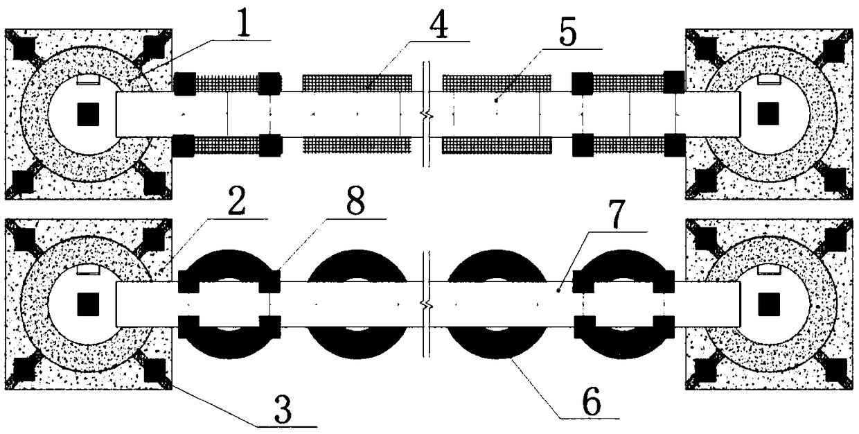
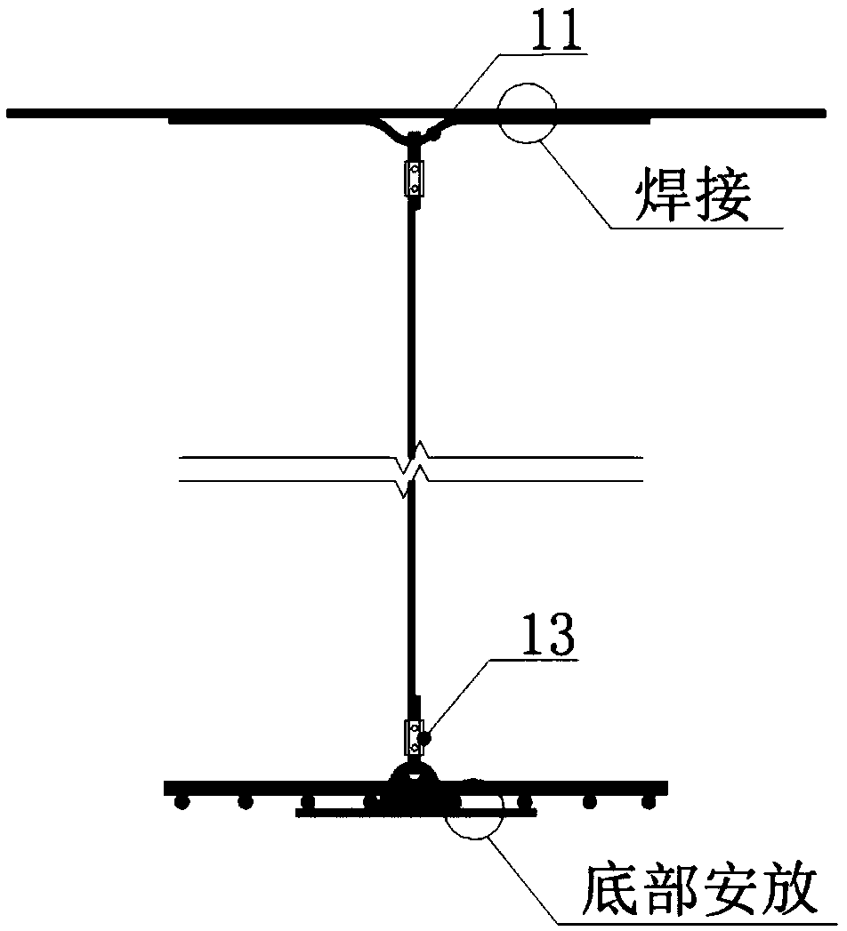
[0056] as attached Figures 1 to 11 Shown, a sandbar sewage pipe, well anti-floating system, including anti-floating plate, bundle wire 5, wire rib 12, steel mesh 8, U groove bar 11, steel plate buckle 14, staple 13, wire rope 9, The anti-floating plate is set at the bottom of the pipe and bound together with the pipe through the bundle wire. The wire ribs are inserted inside the wire bundle to increase the binding surface with the pipe. The steel mesh is set under the pipe and the sewage well, and the steel mesh 8 is welded with U groove bars 11 or steel plate buckles 14, and the U groove bars 11 are not only welded with the mesh surface of the steel mesh, but also bound or welded with the foundation steel bars 10 of the well floor; the steel plate buckles 14 are welded on the steel mesh 8 On or from the bottom of the steel mesh sheet 8;

[0057] The bottom slab foundation steel bars 10 are set on the well bottom slab foundation 2. There are two types of well bottom slab fou...

Embodiment 2

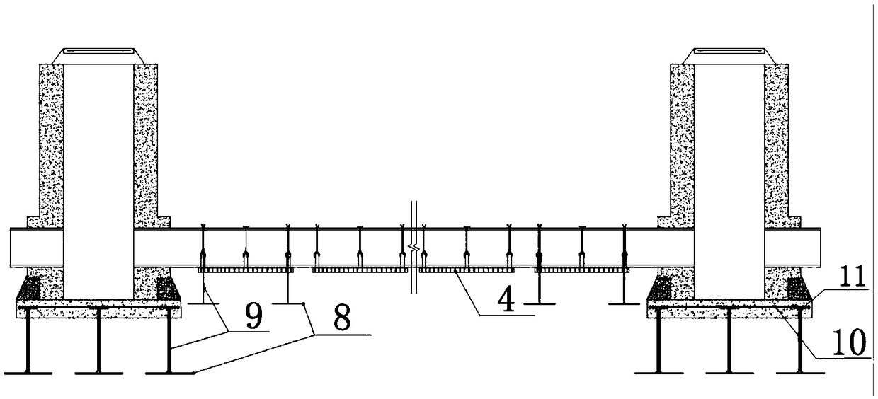
[0069] This embodiment provides a construction method for sandbar sewage pipes and well anti-floating systems. The specific steps are: a. supporting precipitation and trench excavation; b. making and placing steel mesh 8; c. binding drawing wire 9 and backfilling of wool and gravel layer 18; d, completion of surface treatment of wool and gravel layer 18; e, placement and fixing of anti-floating boards; f, laying of pipes and binding and fixing; g, binding and installation of drainage well steel bars; h, drawing wire rope 9 Bind the U groove bar 11, and bind or weld the U groove bar 11 and the foundation steel bar; i, formwork pouring of the drainage well; j, backfilling of the fine sand layer 20 of the pipeline; k, backfilling of the remaining soil layer of the pipeline; l, demoulding of the drainage well , Well wall 1 backfill soil backfill.

[0070] Specifically, the detailed steps of a sandbar sewage pipe and well anti-floating system construction method are as follows:

...


PUM


Abstract

The invention discloses a sandbar sewage pipe, well anti-floating system, include anti-float plates, Bundle wire, clip rib, steel mesh, U-groove ribs, steel plate fasteners, Staples, bracing ropes, Anti-float plate are arranged at that bottom of the pipeline and bind to the pipeline through bundle wires, A loc wire rib is inserted into that inn side of the bundle wire, and a binding surface with the pipe is added. The steel bar mesh sheet is arranged below the pipe and below the sewage well. The steel bar mesh sheet is welded with U-groove reinforcement or steel plate buckle, and the U-groovereinforcement is not only welded with the mesh surface of the steel bar mesh sheet, but also bound or welded with the reinforcement of the bottom plate foundation; The steel plate buckle is welded onthe reinforcing bar mesh sheet or pierced from the bottom of the reinforcing bar mesh sheet; The clasp binds the wire drawing rope to the pipe, the U-groove rib and the steel plate fastener. The claspbinds the wire drawing rope to the pipe, the U-groove rib and the steel plate fastener. The invention also discloses a construction method of the sandbar sewage pipe and the well anti-floating system. The invention changes the traditional method of deep burying, increasing dead weight and increasing fixed foundation, and provides a stable and safe anti-floating system and construction method forsandbar high-water-level pipe and well construction.

Description

technical field [0001] The invention relates to a pipe and well anti-floating system, in particular to a sandbar sewage pipe and well anti-floating system and a construction method. Background technique [0002] With the rapid development of my country's urban infrastructure, more and more developments have been made in sandbanks and tidal flats near the river and coast. With the construction of pipes and wells in high water level and sandy soil environments, construction difficulties in the new geological environment are also increasing. highlight. [0003] The groundwater level of the sandbar is high, the cohesiveness of sand and soil is poor, it is easy to loosen, and the attachment and anti-floating ability is poor. The pipes and wells are basically at a constant water level. Improper pumping and drainage of pit water, rising groundwater level during layered filling, and insufficient floating soil pressure will cause the pipeline to be turned over directly; at the same t...

Claims


Application Information

Patent Timeline
Patent Type & Authority Applications(China)
IPC IPC(8): E02D3/10E02D19/10E02D31/12
CPCE02D3/10E02D19/10E02D31/12
Inventor 夏志聪赵海莲马越张志海张帆
Owner CHINA FIRST METALLURGICAL GROUP
Why Eureka
Try Eureka