Building brick cutting machine

A brick cutting machine and construction technology, applied in stone processing tools, work accessories, manufacturing tools, etc., can solve the problems of easy hand injury and labor

Inactive Publication Date: 2019-10-15
周忆梅
View PDF6 Cites 3 Cited by
  • Summary
  • Abstract
  • Description
  • Claims
  • Application Information

AI Technical Summary

Problems solved by technology

[0003] In order to overcome the disadvantages that the human hand needs to continuously swing the tool to cut the brick, which is laborious, and the hand needs to hold the brick to fix it, and the tool is easy to knock the hand. Therefore, the technical problem of the present invention is: to provide a A building brick cutting machine that can replace people to cut bricks, saves labor, and will not be injured by tools

Method used


Image

  • Building brick cutting machine
  • Building brick cutting machine
  • Building brick cutting machine

Examples


Embodiment 1

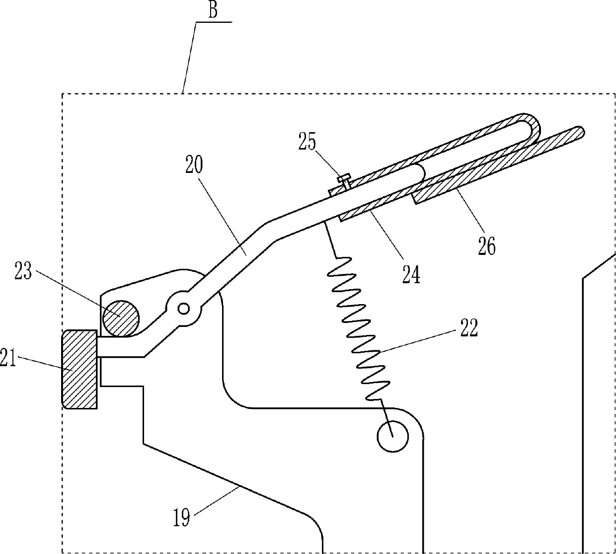
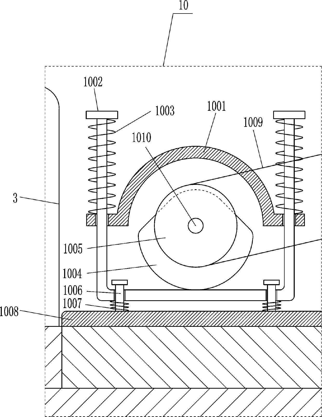
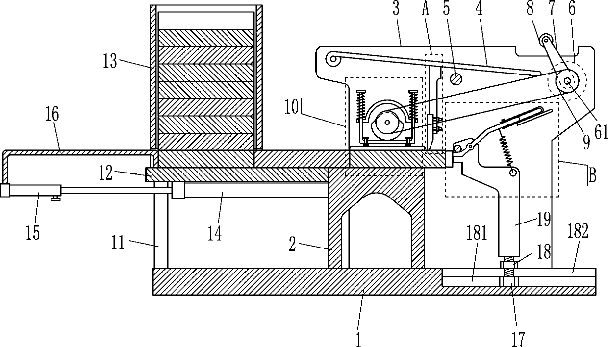
[0017] A construction brick cutter, such as Figure 1-3 As shown, it includes a base 1, a workbench 2, a first mounting plate 3, a spring plate 4, a mounting rod 401, a press knife 402, a first limit block 5, a motor 6, a first rotating shaft 61, a swing rod 7, and a roller 8. The first belt wheel 9 and the pressing mechanism 10, the top middle of the base 1 is fixedly connected with a workbench 2 where bricks can be placed, the base 1 is connected to the workbench 2 by welding, and the top right rear of the base 1 is fixed Connected to the first mounting plate 3, the first mounting plate 3 is located on the back side of the workbench 2 in contact with it. The upper left part of the front side of the first mounting plate 3 is provided with a pressing mechanism 10 that can compress bricks. Located above the workbench 2, the upper right part of the first mounting plate 3 is rotatably connected with a first rotating shaft 61. The front end of the first rotating shaft 61 is equipped...

Embodiment 2

[0019] A construction brick cutting machine, such as Figure 1-3 As shown, it includes a base 1, a workbench 2, a first mounting plate 3, a spring plate 4, a mounting rod 401, a press knife 402, a first limit block 5, a motor 6, a first rotating shaft 61, a swing rod 7, and a roller 8. The first belt wheel 9 and the pressing mechanism 10, the middle of the top of the base 1 is fixed with a workbench 2 where bricks can be placed, and the first mounting plate 3 and the first mounting plate 3 are fixed at the right rear of the top of the base 1 Located on the back side of the workbench 2 in contact with it, the upper left part of the front side of the first mounting plate 3 is provided with a pressing mechanism 10 that can compact the bricks. The pressing mechanism 10 is located above the workbench 2, and the right part of the first mounting plate 3 The upper side is rotatably connected with a first rotating shaft 61. A first pulley 9 is installed at the front end of the first rota...

Embodiment 3

[0022] A construction brick cutting machine, such as Figure 1-3 As shown, it includes a base 1, a workbench 2, a first mounting plate 3, a spring plate 4, a mounting rod 401, a press knife 402, a first limit block 5, a motor 6, a first rotating shaft 61, a swing rod 7, and a roller 8. The first belt wheel 9 and the pressing mechanism 10, the middle of the top of the base 1 is fixed with a workbench 2 where bricks can be placed, and the first mounting plate 3 and the first mounting plate 3 are fixed at the right rear of the top of the base 1 Located on the back side of the workbench 2 in contact with it, the upper left part of the front side of the first mounting plate 3 is provided with a pressing mechanism 10 that can compact the bricks. The pressing mechanism 10 is located above the workbench 2, and the right part of the first mounting plate 3 The upper side is rotatably connected with a first rotating shaft 61. A first pulley 9 is installed at the front end of the first rota...


PUM


Abstract

The invention relates to a brick cutting machine, in particular to a building brick cutting machine. The invention aims to provide the building brick cutting machine, wherein the building brick cutting machine is characterized by being capable of replacing workers to cut off bricks, so that labor is saved, and hands cannot be knocked and hurt by a tool. According to the technical description scheme, the building brick cutting machine comprises a base, a workbench, a first mounting plate, an elastic plate, a mounting rod, a pressing cutter, a first limiting block, a motor, a first rotating shaft, a swing rod, rollers and the like; and the workbench for placing the bricks is fixedly connected to the middle of the top of the base, the first mounting plate is fixedly connected to the rear partof the right side of the top of the base, and the first mounting plate is located on the rear side of the workbench and is in contact with the workbench. According to the building brick cutting machine, the bricks are placed on the workbench, the motor is started to rotate forwards, so that the bricks can be pressed and fixed by a pressing plate, then the pressing cutter moves downwards to cut off the bricks, so that the bricks are fixed without holding the tool with the hands by people, more labor is saved, and the hands can be prevented from being knocked and hurt by the tool.

Description

Technical field [0001] The invention relates to a brick cutting machine, in particular to a building brick cutting machine. Background technique [0002] In building construction, a lot of materials need to be used. Bricks can be used to build walls, but some places need to be filled with shorter bricks. The bricks need to be cut to a suitable length. Usually people hold them by hand. The tool cuts the brick. Because the human hand needs to constantly wave the tool to cut the brick, it is more laborious, and the brick needs to be held down to fix it. The tool is easy to damage the hand, so people will use heavy objects to cut the brick. The block is pressed and fixed, and the block is cut off for a period of time and then rested for a while. This is inefficient and troublesome. Summary of the invention [0003] In order to overcome the shortcomings that human hands need to constantly wave the tool to cut the bricks, it is more laborious, and the bricks need to be pressed to fix t...

Claims


Application Information

Patent Timeline
Patent Type & Authority Applications(China)
IPC IPC(8): B28D1/22B28D7/00B28D7/04
CPCB28D1/222B28D7/00B28D7/04
Inventor 周忆梅
Owner 周忆梅
Why Eureka
Try Eureka