Conveying mechanism

A technology for conveying mechanisms and gaskets, which is applied to conveyor objects, furnaces, lighting and heating equipment, etc., can solve problems such as difficult management, yield loss, and cumbersome processes, so as to avoid wasting production capacity, save production costs, and improve production. The effect of efficiency

Inactive Publication Date: 2019-10-15
SHENZHEN CHINA STAR OPTOELECTRONICS SEMICON DISPLAY TECH CO LTD
View PDF8 Cites 1 Cited by
  • Summary
  • Abstract
  • Description
  • Claims
  • Application Information

AI Technical Summary

Problems solved by technology

[0005] An object of the present invention is to provide a transfer mechanism, which can solve the problems of waste o

Method used


Image

  • Conveying mechanism
  • Conveying mechanism
  • Conveying mechanism

Examples


Embodiment 1

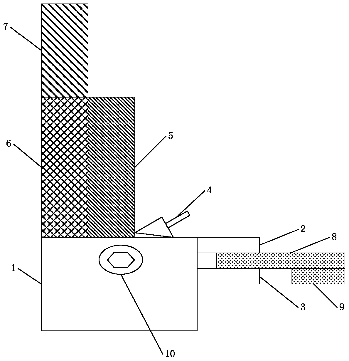
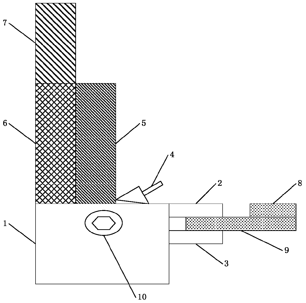
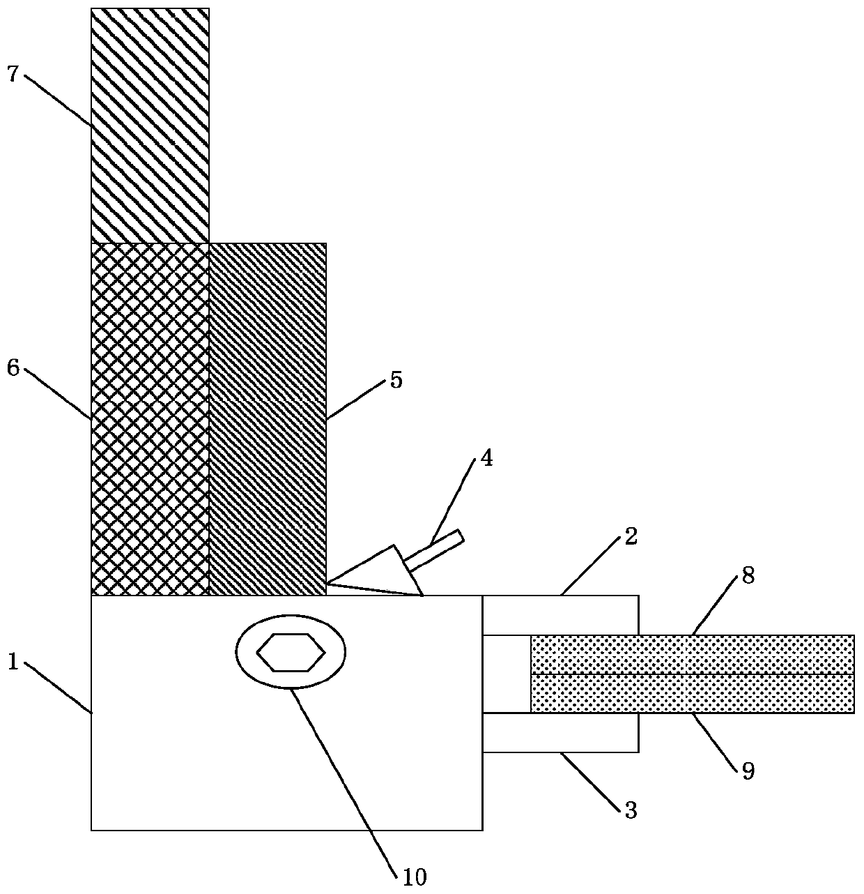
[0036] Such as figure 1 As shown, the working schematic diagram of the existing conveying mechanism Figure 1 , wherein the conveying mechanism includes: a sheet metal block 1, an upper splint 2, a lower splint 3, a set screw 4, a cylinder control device 5, a fixing device 6 and a motor control device 7.

[0037] Wherein the upper splint 2 is connected to the sheet metal block, and the lower splint 3 is connected to the sheet metal block 1 through the connecting shaft 10, so that the upper splint 2, the connecting shaft 10 and the lower splint form a Scissor-like gripping device. The air cylinder control device 5 is arranged on the sheet metal block 1 , and the conveying mechanism controls the upper splint 2 and the lower splint 3 to grip and cut the panel through the air cylinder control device 5 .

[0038] Wherein the set screw 4 is arranged on the sheet metal block 1 , and the conveying mechanism controls the distance between the upper splint 2 and the lower splint 3 thro...


PUM

PropertyMeasurementUnit
Lengthaaaaaaaaaa

Abstract

The invention relates to a conveying mechanism, wherein an upper gasket is arranged on the surface, facing a lower clamping plate, of an upper clamping plate, and the upper gasket comprises a first upper gasket and a second upper gasket. Therefore, the conveying mechanism can be adapted to different modes of clamping a single panel and clamping double panels, so that the manual adjustment of the distance between the upper clamping plate and the lower clamping plate is avoided, the problems that the productivity is wasted, the management is not easy, the process is complicated, and the yield islost are avoided, and finally the effects of saving the production cost and improving the production efficiency are achieved.

Description

technical field [0001] The invention relates to the field of display device manufacturing, in particular to a conveying mechanism. Background technique [0002] Active thin film transistor liquid crystal display (Thin Film Transistor-LCD, TFT-LCD) has been developed rapidly and widely used in recent years. Most of the liquid crystal display devices currently on the market are backlight liquid crystal display devices, which include a liquid crystal display panel and a backlight module. Usually, the liquid crystal display panel consists of a color filter substrate (Color Filter, CF), a thin film transistor substrate (Thin Film Transistor, TFT), a liquid crystal (Liquid Crystal, LC) sandwiched between the color filter substrate and the thin film transistor substrate, and a sealant ( Sealant) composition; its working principle is to control the rotation of the liquid crystal molecules in the liquid crystal layer by applying a driving voltage on the two glass substrates, and ref...

Claims


Application Information

Patent Timeline
IPC IPC(8): B65G49/06
CPCB65G49/067
Inventor 高杰
Owner SHENZHEN CHINA STAR OPTOELECTRONICS SEMICON DISPLAY TECH CO LTD
Why Eureka
Try Eureka