Cutting equipment for packaging box raw paper processing

A packaging box and base paper technology, applied in the directions of transportation and packaging, winding strips, sending objects, etc., can solve the problems of difficult maintenance, difficult access, blade wear, etc., and achieve the effect of convenient maintenance and replacement, and convenient cutting knife.

Inactive Publication Date: 2019-10-15
安徽文博纸品印刷有限公司
17 Cites 1 Cited by

AI-Extracted Technical Summary

Problems solved by technology

[0004] The purpose of the present invention is to provide a cutting device for packaging base paper processing, to solve the above-mentioned problems that the length of paper cutting cannot be accurat...

Abstract

The invention discloses cutting equipment for packaging box raw paper processing in the field of raw paper processing. An L-shaped plate, scales, infrared receivers, an infrared transmitter and an electric pushing rod are arranged, packaging raw paper falls when the packaging raw paper moves to the end of a conveyer belt along with the conveyer belt, the infrared transmitter is shielded when the packaging raw paper falls to a certain height, the infrared receivers can not receive infrared rays, then a control box receives a signal and controls an air cylinder to move downwards to drive a kniferest to move downwards, the packaging raw paper is cut by a cutting knife, the cut packaging raw paper falls to the top of a base, the infrared receivers receive the infrared rays, the control box receives the signal and controls the air cylinder to contract upwards, the steps are repeatedly conducted, and then precise cutting of the packaging raw paper is achieved; the cutting knife clamped to the bottom of the knife rest is arranged, and the cutting knife can be conveniently overhauled and replaced; and an extrusion rod containing cooling liquid is arranged, and therefore the raw paper canbe flattened and cooled.

Application Domain

Technology Topic

Image

  • Cutting equipment for packaging box raw paper processing
  • Cutting equipment for packaging box raw paper processing
  • Cutting equipment for packaging box raw paper processing

Examples

  • Experimental program(1)

Example Embodiment

[0023] The technical solutions in the embodiments of the present invention will be clearly and completely described below in conjunction with the accompanying drawings in the examples of the present invention. Obviously, the described embodiments are only a part of the embodiments of the present invention, rather than all the embodiments. Based on the embodiments of the present invention, all other embodiments obtained by those of ordinary skill in the art without creative work shall fall within the protection scope of the present invention.
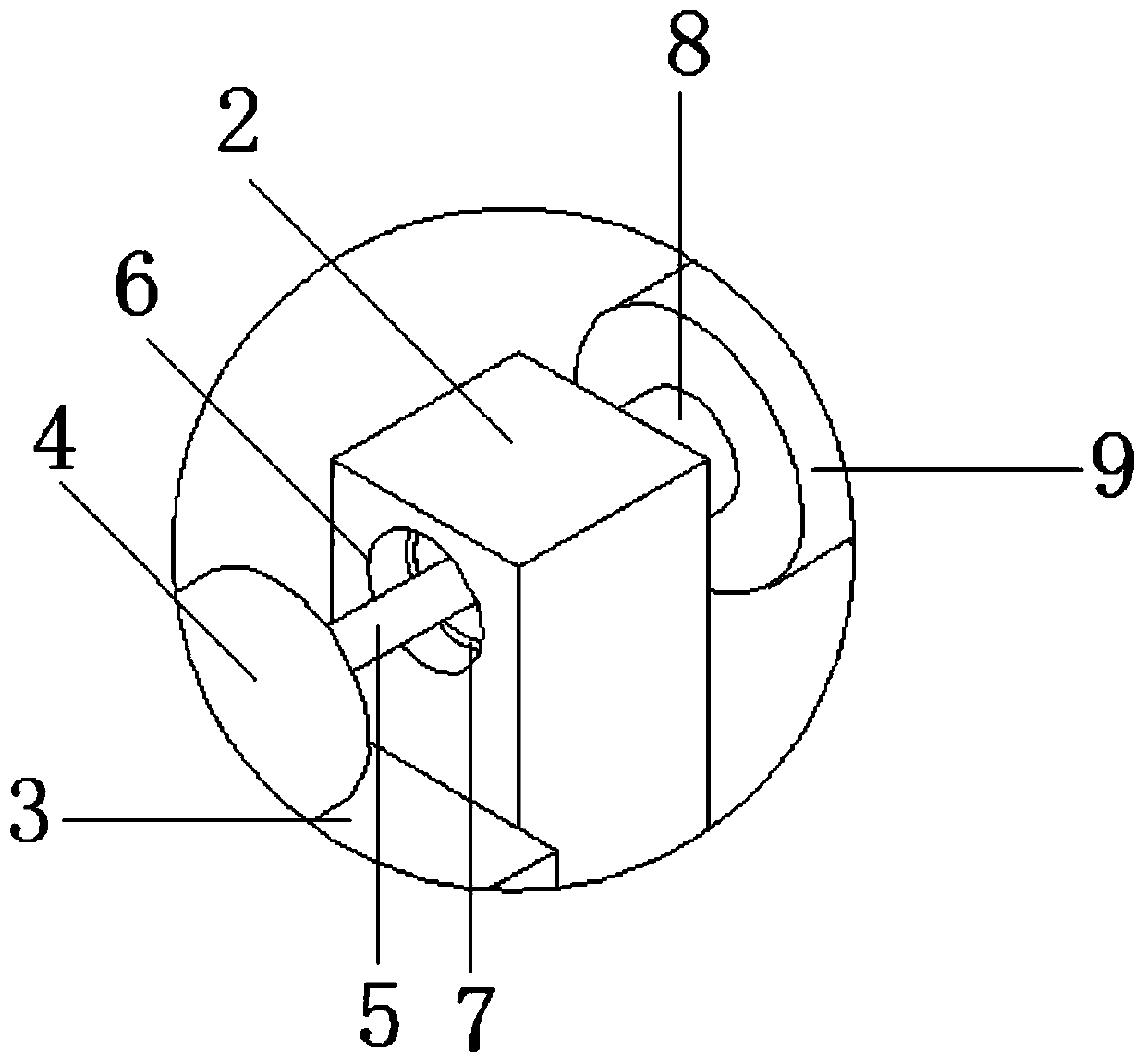
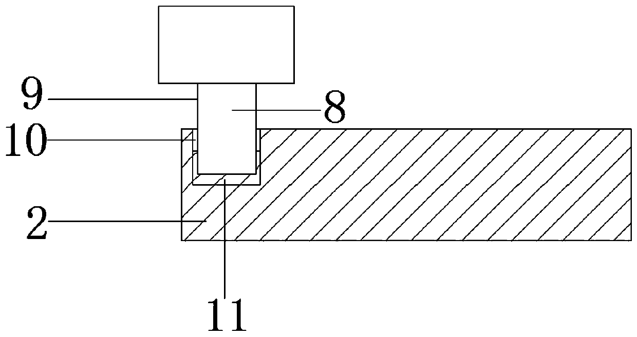
[0024] See Figure 1-6 , The present invention provides a technical solution: a cutting device for processing raw paper for packaging boxes, comprising a base 1 and a control box 26, the control box 26 is located at the top edge of the base 1, the side of the control box 26 is provided with an operation panel 260, the base 1 Two sets of first support rods 2 are symmetrically fixedly installed at one end of the top, a rotating shaft 8 is rotatably connected between the first support rods 2, and a transmission roller 9 is fixedly connected to the outer wall of the rotating shaft 8, and a motor base 3 is provided on one side of the first support rod 2. The motor base 3 is fixedly installed on the base 1. A motor 4 is arranged on the top of the motor base 3, and the end of the motor 4 is connected with a motor shaft 5. The first support rod 2 close to the motor 4 is projected forward on the first support rod 2 on the motor shaft 5 A through hole 6 is opened at the position of the through hole 6, a first bearing 7 is provided in the through hole 6, and the first bearing 7 is rotatably connected to the shaft 8. The end of the motor shaft 5 is fixedly connected with one end of the shaft 8 through the first bearing 7 and the other end of the shaft 8 rotates. Connected to the first support rod 2 far away from the motor 4, the first support rod 2 far away from the motor 4 is provided with a circular groove 10 at the position where the through hole 6 is projected forwardly. The circular groove 10 is provided with a second bearing 11 and a rotating shaft 8 The other end is rotatably connected to the first support rod 2 away from the motor 4 through the second bearing 11. An electric push rod 12 is provided on one side of the first support rod 2. The electric push rod 12 is fixedly connected to the top of the base 1, and the electric push rod 12 is movable inside Connected to the piston rod 120, the piston rod 120 is fixedly installed with an infrared emitter 13 on the side close to the first support rod 2. The other side of the first support rod 2 is provided with four sets of second support rods 14, and the second support rods 14 are fixed It is mounted on the top of the base 1, a transmission belt 15 is arranged between the second support rods 14. The two ends of the transmission belt 15 are fixed by rollers 16, and both ends of the roller 16 are rotated by the third bearing 17 and the second support rod 14. The top of the transmission belt 15 is close to the end of the first support rod 2 is provided with an extrusion rod 18, the bottom of the extrusion rod 18 is fixedly connected with a connecting rod 19, and one end of the connecting rod 19 is fixedly connected to the top of the second support rod 14. There is an L plate 20 on the side of the belt 15. The L plate 20 is fixedly installed on the top of the base 1, and the bottom of the horizontal part of the L plate 20 is fixedly installed with a cylinder 21. The end of the cylinder 21 is fixedly connected with a knife holder 22, and the bottom of the knife holder 22 is clamped. A scale 24 is provided on the side of the cutting knife 23 and the vertical part of the L plate 20 close to the second support rod 14, and an infrared receiver 25 is fixedly installed in the middle of each scale line of the scale 24.
[0025] Among them, the control box 2, the motor 4, the electric push rod 12, the infrared transmitter 13, the transmission belt 15, the cylinder 21 and the infrared receiver 25 are electrically connected to the power source, and the controller 2 electrically controls the motor 4, the electric push rod 12, and infrared The transmitter 13, the transmission belt 15, the cylinder 21 and the infrared receiver 25 work; the height of the first support rod 2 is higher than the height of the second support rod 14, so that the height of the transmission roller 9 is higher than that of the transmission belt 15 Height, the height difference is used to prevent the base paper from wrinkling. The length of the conveying roller 9 is less than the distance between the two first support rods 2 to ensure that the base paper will not rub against the first support rod 2 during the conveying process, which will cause the base paper to move and affect Cutting effect; the depth of the circular groove 10 is half the width of the first support rod 2; the second support rods 14 are arranged in a rectangle, and the height of the top of the transmission belt 15 is higher than the top of the second support rod 14 and smaller than the first support rod 2 At the top, the conveyor belt 15 is made of cutting-resistant material; the cutting knife 23 and the edge of the conveyor belt 15 close to the L plate 20 are on the same vertical plane; the top of the scale 24 and the top of the conveyor belt 15 are on the edge close to the L plate 20 The same horizontal plane; the extrusion rod 18 is a hollow rod with cooling liquid inside. When the raw paper passes through the extrusion rod 18, it is squeezed and leveled and cooled.
[0026] A specific application of this embodiment is: controlling the telescopic height of the electric push rod 12 through the operation panel 260 on the controller 26, thereby controlling the height of the infrared transmitter 13, starting all the electrical components of the device, and wrapping the original paper through The conveying roller 9 is transferred to the conveying belt 15. There is a height difference between the conveying roller 9 and the conveying belt 15, which makes the wrapping paper and the horizontal plane have a certain angle to prevent the packing box paper from wrinkling. At the same time, a squeeze rod 18 is provided above the end of the conveying belt 15 , The squeeze rod 18 is equipped with coolant, and the raw paper of the packaging box is squeezed and cooled by the squeeze rod 18 to further ensure that the raw paper of the packaging box has no wrinkles. With the movement of the conveyor belt 15, the raw paper of the packaging box moves to the conveyor belt 15 At the end, the original paper of the packing box falls. When the original paper of the packing box falls to a certain height, the infrared emitter 13 is blocked, and the infrared receiver 25 cannot receive infrared rays. At this time, the control box 26 receives the signal and controls the cylinder 21 to move downwards to drive The knife holder 22 moves downwards, so that the cutting knife 23 cuts the raw paper of the packing box. After cutting, the wrapped raw paper falls on the top of the base 1, the infrared receiver 25 receives the infrared, and the control box 26 receives a signal to control the cylinder 21 to shrink upward , Repeat the above steps to cut the original packaging paper.
[0027] In the description of this specification, the description with reference to the terms "one embodiment", "example", "specific example", etc. means that the specific feature, structure, material or characteristic described in combination with the embodiment or example is included in at least the present invention. In one embodiment or example. In this specification, the schematic representations of the above terms do not necessarily refer to the same embodiment or example. Moreover, the described specific features, structures, materials or characteristics may be combined in any one or more embodiments or examples in a suitable manner.
[0028] The preferred embodiments of the present invention disclosed above are only used to help explain the present invention. The preferred embodiment does not describe all the details in detail, nor does it limit the invention to only the described specific embodiments. Obviously, many modifications and changes can be made according to the content of this manual. This specification selects and specifically describes these embodiments in order to better explain the principles and practical applications of the present invention, so that those skilled in the art can understand and use the present invention well. The present invention is only limited by the claims and their full scope and equivalents.

PUM

no PUM

Description & Claims & Application Information

We can also present the details of the Description, Claims and Application information to help users get a comprehensive understanding of the technical details of the patent, such as background art, summary of invention, brief description of drawings, description of embodiments, and other original content. On the other hand, users can also determine the specific scope of protection of the technology through the list of claims; as well as understand the changes in the life cycle of the technology with the presentation of the patent timeline. Login to view more.

Similar technology patents

Biconical high consistency refiner

InactiveCN103924472ASimplify design and installationEasy to repair and replacePulp beating/refining methodsStatorAxial length
Owner:TIANJIN UNIVERSITY OF SCIENCE AND TECHNOLOGY

Classification and recommendation of technical efficacy words

Why Eureka
Try Eureka