Buffer device and buffer control method for rocket flexible cable erection system

A technology of flexible steel cables and buffer devices, applied in the field of buffer devices, can solve the problems such as the inability of hydraulic cylinders to achieve redundant backup, the inability to provide reverse thrust, the damage to the quiver combination or the launch platform, etc.

Active Publication Date: 2021-08-27
BEIJING INST OF SPACE LAUNCH TECH +1
View PDF5 Cites 0 Cited by
  • Summary
  • Abstract
  • Description
  • Claims
  • Application Information

AI Technical Summary

Problems solved by technology

As for the offshore launch platform, due to the limitation of the distance between the rotary shaft and the space of the launching ship, the hydraulic cylinder is no longer suitable as the actuator of the erection system; and the dynamic environment at sea is more complex, the hydraulic cylinder cannot realize redundant backup, and the safety is poor
In view of this, the electric winch flexible steel cable erecting system has become an optional method, but this erecting system has the following problems in the implementation and application: because the flexible steel cable can only provide one-way pulling force and cannot provide reverse thrust, the lifting During the vertical process, when the overall center of mass of the erection stand and the quiver assembly crosses the vertical plane where the rotary axis is located, a stall phenomenon will occur. If it is not controlled, it will seriously affect the safety of the rocket and the launch stand. If a mechanical limit is adopted, it will Can create impact issues, as well as cause damage to quiver assemblies or launch pads

Method used


Image

  • Buffer device and buffer control method for rocket flexible cable erection system
  • Buffer device and buffer control method for rocket flexible cable erection system
  • Buffer device and buffer control method for rocket flexible cable erection system

Examples


Embodiment Construction

[0027] First of all, it needs to be explained that the orientation words such as up, down, left, right, front, and back described in the present invention are only described according to the accompanying drawings, so as to facilitate understanding, and are not intended to limit the technical solution and scope of protection of the present invention. .

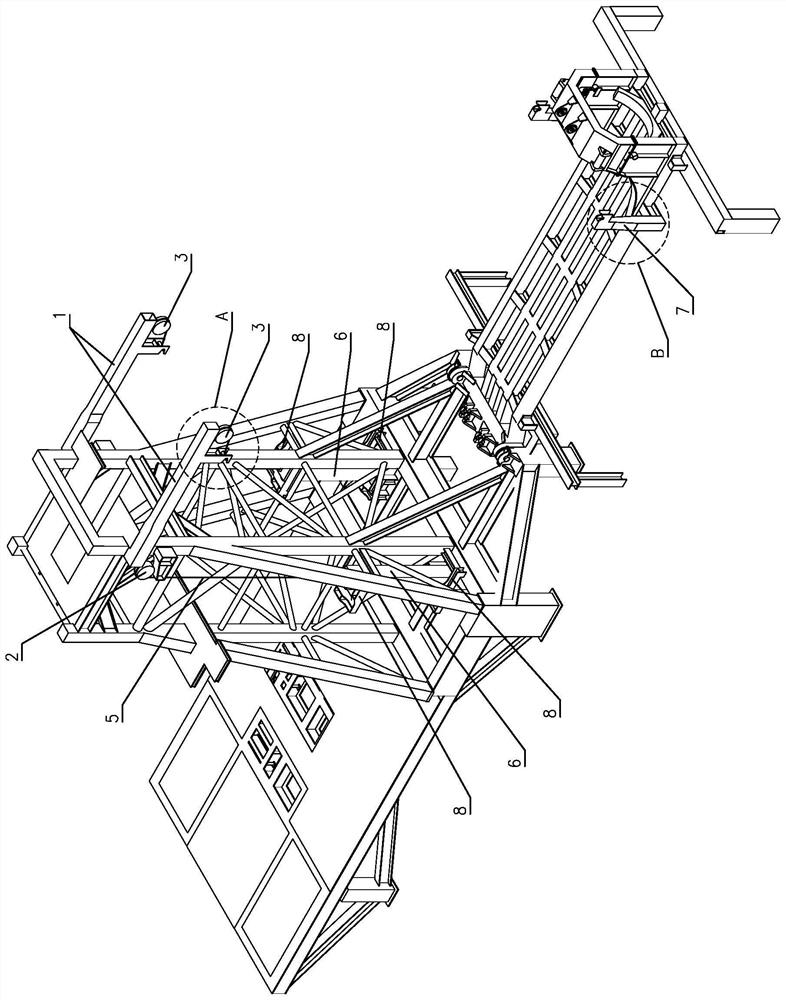
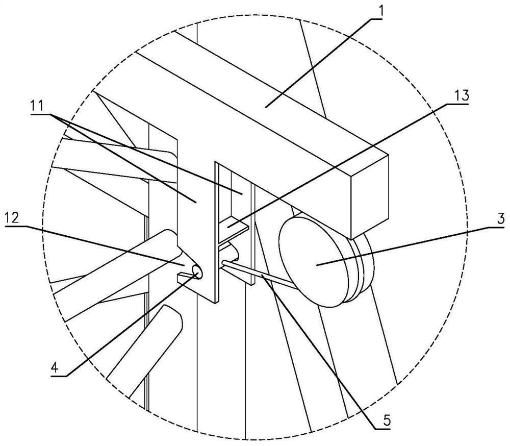
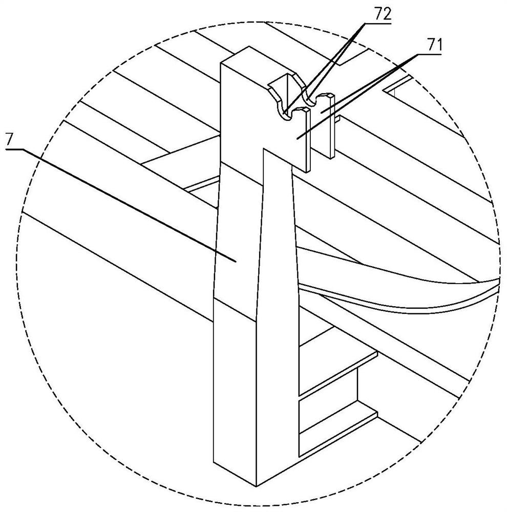
[0028] Such as Figure 1 to Figure 6The shown specific implementation of the cushioning device of the present invention for the rocket flexible cable erection system includes a cushioning mechanism arranged on the fixed frame 101 and a docking mechanism arranged on the erecting frame 102 . The buffer mechanism is provided with a support arm 1, a guide pulley 2, a reversing pulley 3, a limit rod 4, a traction rope 5 and a pendant 6. Let the support arm 1 be set horizontally and fix the left end on the right side of the fixed frame 101, and fix two front and back spaced spacing plates 11 on the lower side of the right half of th...


PUM


Abstract

The invention relates to a buffer device and a buffer control method for a rocket flexible steel cable erecting system. The buffer device includes a buffer mechanism and a docking mechanism. The buffer mechanism includes a support arm, a guide pulley, a reversing pulley, a limit lever, a traction rope and a pendant The support arm is fixed on the fixed frame, the support arm is fixed with two limit plates, and the two limit plates are provided with limit card slots, the guide pulley is installed on the fixed frame, the reversing pulley is installed on the support arm, and the guide pulley Corresponding to the reversing pulley, it is located on the left and right sides of the limit plate. The limit rod is located in the limit slot of the limit plate and connected to one end of the traction rope. The other end of the traction rope bypasses the reversing pulley, the guide pulley and the pendant. Connection; the docking mechanism includes a docking arm fixed on the erecting frame, two docking plates are fixed on the upper end of the docking arm, and a docking card slot is provided on the upper side of the two docking plates. The utility model has the advantages of simple structure, smooth action and good cushioning effect. The buffer control method has the advantages of simple process and easy implementation.

Description

technical field [0001] The invention relates to a buffer device, in particular to a heavy object buffer device used in a rocket flexible cable erection system and a buffer control method thereof. Background technique [0002] In the field of rocket launching, the launch platform is usually designed to be composed of a fixed frame and a vertical frame, and the two are hinged through the rotary shaft, so that the quiver assembly (the combination of the rocket and the launch tube) is hoisted and fixed on the vertical frame. on the frame, and through the erecting system, the erecting frame is rotated around the rotary axis to complete the erecting action of the rocket. For the traditional land launch platform, the actuator of the erection system usually adopts a hydraulic cylinder, because the hydraulic cylinder is a two-force rod structure, which can provide both pulling force and thrust force, and the speed can be controlled by the hydraulic damping buffer structure to achieve...

Claims


Application Information

Patent Timeline
Patent Type & Authority Patents(China)
IPC IPC(8): F41F3/04
CPCF41F3/04
Inventor 姜续何轩周彤何丽张涛华张云巧凌霄秦利王丽
Owner BEIJING INST OF SPACE LAUNCH TECH
Why Eureka
Try Eureka