Electronic controller test system and method
A technology of electronic controller and test system, which is applied in the direction of faulty hardware test method, transmission system, comprehensive factory control, etc., and can solve problems such as difficulty in judging the source of faults, occasional software faults, irregular writing specifications, etc.
- Summary
- Abstract
- Description
- Claims
- Application Information
AI Technical Summary
Problems solved by technology
Method used
Image
Examples
Embodiment 1
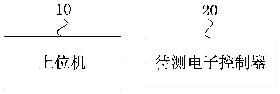
[0050] figure 1 It is a schematic structural diagram of an electronic controller testing system provided by Embodiment 1 of the present invention. This embodiment is applicable to the case of testing the driving control function of the electronic controller in the vehicle.
[0051] Such as figure 1 As shown, the system includes: a host computer 10 and an electronic controller 20 to be tested, and the host computer 10 and the electronic controller 20 to be tested are connected by a controller area network CAN bus; Send the CAN bus data; the electronic controller 20 to be tested is used to classify and analyze the CAN bus data to obtain CAN information, generate a driving signal based on the automotive open system architecture constructed according to the CAN information, and execute the described drive signal to obtain corresponding waveform data; the host computer 10 is also used to generate test results for the waveform data corresponding to the drive signal.
[0052] Spec...
Embodiment 2
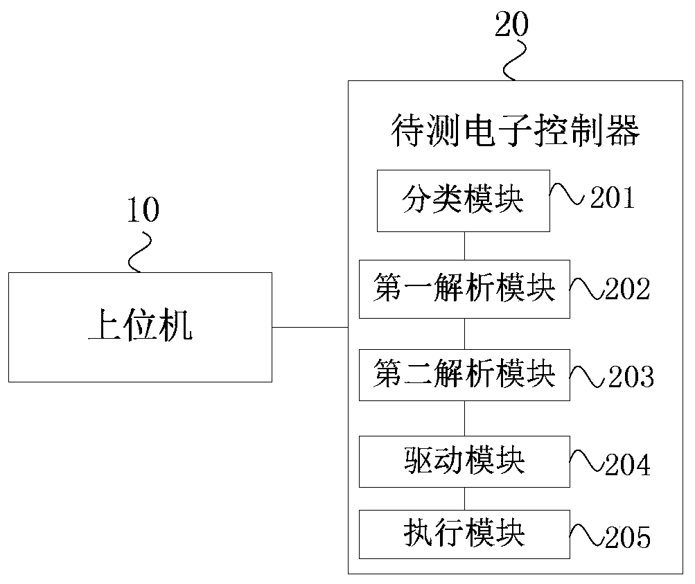
[0057] figure 2 It is a schematic structural diagram of an electronic controller testing system provided by Embodiment 2 of the present invention. This embodiment describes the specific structure and functions of the electronic controller to be tested on the basis of the above-mentioned embodiments. For technical details not described in this embodiment, refer to any of the above-mentioned embodiments.
[0058] Such as figure 2 As shown, the electronic controller 20 to be tested includes: a classification module 201, which is used to determine the data type of the CAN bus data, and the data type includes complex data and simple data; a first analysis module 202, which is used to call The database file analyzes the complex data to obtain CAN information; the second analysis module 203 is used to obtain the analysis instruction input by the user to analyze the simple data to obtain CAN information; the driver module 204 is used to obtain CAN information based on the CAN infor...
Embodiment 3
[0071] Figure 5 It is a flow chart of an electronic controller testing method provided by Embodiment 3 of the present invention, and the electronic controller testing method of this embodiment is applied to a host computer. It should be noted that for technical details not exhaustively described in this embodiment, reference may be made to any of the foregoing embodiments.
[0072] Specifically, such as Figure 5 As shown, the method specifically includes the following steps:
[0073] S310. Send CAN bus data to the electronic controller to be tested, so that the electronic controller to be tested can classify and analyze the CAN bus data to obtain CAN information, and generate a driving signal based on the automotive open system architecture according to the CAN information, and executing the driving signal at a set period to obtain corresponding waveform data;
[0074] S230. Generate a test result for the waveform data corresponding to the driving signal.
[0075] An ele...
PUM
 Abstract
Description
Claims
Application Information
 - R&D
- Intellectual Property
- Life Sciences
- Materials
- Tech Scout
- Unparalleled Data Quality
- Higher Quality Content
- 60% Fewer Hallucinations
Browse by: Latest US Patents, China's latest patents, Technical Efficacy Thesaurus, Application Domain, Technology Topic, Popular Technical Reports.
© 2025 PatSnap. All rights reserved.Legal|Privacy policy|Modern Slavery Act Transparency Statement|Sitemap|About US| Contact US: help@patsnap.com


