Inner hole positioning device, inner hole positioning method and climbing mechanism

A technology of positioning device and inner hole, which is applied in the field of hole positioning, can solve the problems such as the limitation of the load capacity of the positioning device, damage, and the inability to remove the positioning device, so as to improve the service life and safety, avoid the falling of balls and petals, and improve the The effect of the locking positioning effect

Active Publication Date: 2019-10-15
HARBIN ENG UNIV
View PDF13 Cites 0 Cited by
  • Summary
  • Abstract
  • Description
  • Claims
  • Application Information

AI Technical Summary

Problems solved by technology

With the development of detection devices, the carrying capacity of existing positioning devices is insufficient, and there is an urgent need for a positioning device with large carrying capacity, reliable structure and light weight
Since the inner hole of the tube sheet is a round hole, the currently used positioning device cannot reliably adapt to the inner hole of the tube sheet, resulting in uneven stress on the inner hole and damage; Air pressure, under the action of the spring reaction force, the claws will directly collide with the tube sheet, resulting in damage to the positioning device and the tube sheet; there is a large amount of debris accumulation in the inner hole of the tube sheet, which will increase the great resistance during the insertion process of the positioning dev

Method used


Image

  • Inner hole positioning device, inner hole positioning method and climbing mechanism
  • Inner hole positioning device, inner hole positioning method and climbing mechanism
  • Inner hole positioning device, inner hole positioning method and climbing mechanism

Examples


Example Embodiment

[0034] The technical solutions in the embodiments of the present invention will be clearly and completely described below in conjunction with the embodiments of the present invention. Apparently, the described embodiments are only some of the embodiments of the present invention, not all of them. Based on the embodiments of the present invention, all other embodiments obtained by persons of ordinary skill in the art without making creative efforts belong to the protection scope of the present invention.

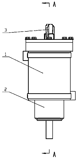
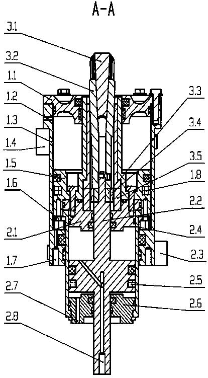
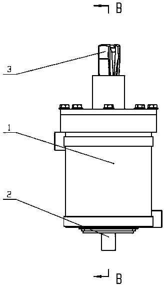
[0035] like Figure 1-4 As shown, the inner hole positioning device of the present invention includes an upper cylinder 1, a lower cylinder 2 and claws 3, the upper cylinder 1 includes an upper cylinder liner 1.3, and the top of the upper cylinder liner 1.3 is connected with the first cylinder head 1.1, and the top of the upper cylinder liner 1.3 An upper piston 1.5 is installed inside, and an upper cylinder magnetic ring 1.8 is arranged on the upper piston 1.5, and an upper ...


PUM


Abstract

The invention discloses an inner hole positioning device, an inner hole positioning method and a climbing mechanism. A lower air cylinder is arranged in an upper air cylinder, a cylinder cover of thelower air cylinder is connected to a piston rod of the upper air cylinder, a first upper cavity is formed in the top of the piston rod of the upper air cylinder, a first lower cavity is formed in thebottom of the piston rod of the upper air cylinder, a second upper cavity is formed in the top of a piston rod of the lower air cylinder, a second lower cavity is formed in the bottom of the piston rod of the lower air cylinder, and the first upper cavity, the first lower cavity, the second upper cavity and the second lower cavity are separately connected to an inflating pipeline through air via ports; a paw core penetrates through a through hole in the middle of the piston rod of the upper air cylinder, the bottom of the paw core is connected to the cylinder cover of the lower air cylinder, slide blocks sliding axially are arranged on the outer wall of the paw core, reversed L-shaped grooves are formed in the bottoms of the slide blocks, bumps equal to the slide blocks in quantity are arranged on the top of the piston rod of the lower air cylinder, and the dimensions of the bumps fit the reversed L-shaped grooves. The inner hole positioning device provided by the invention is reliablein structure and stable to position an inner hole, prevents positioning failure, is light in weight and large in bearing capacity, and monitors the positioning state in real time.

Description

technical field [0001] The invention belongs to the field of hole positioning technology, and relates to an inner hole positioning device, a positioning method and a crawling mechanism, which are used for steam generator detection and tube plate fixing, positioning in the machining production process, quick clamping and positioning of an automatic production line, and the like. Background technique [0002] The steam generator tube sheet is an important part of the pressure boundary of the primary circuit of a nuclear power plant, and is the main barrier to prevent the leakage of radioactive fission products. Therefore, the inspection of the steam generator tube sheet is a mandatory inspection item for pre-service and in-service inspections of nuclear power plants. At present, the detection devices of steam generators used in various countries are different, but most of them use positioning devices to fix the detection devices on the tube sheet. This requires that the positi...

Claims


Application Information

Patent Timeline
IPC IPC(8): G21C17/01G21C17/013G21C17/017
CPCG21C17/01G21C17/013G21C17/017Y02E30/30
Inventor 李思岑王刚贾鹏张瓴宇唐钦云王立权王畅张国成赵伟浩王天昊
Owner HARBIN ENG UNIV
Why Eureka
Try Eureka