
A method of making a Schottky

A manufacturing method, dry etching technology, applied in the direction of final product manufacturing, sustainable manufacturing/processing, semiconductor/solid-state device manufacturing, etc., can solve problems such as high processing costs, affecting product profitability, and non-contribution, and achieve improvement Productivity, reduction of overlay requirements, and improvement of production efficiency

Active Publication Date: 2022-07-08
TIANJIN HUANXIN TECH DEV
View PDF0 Cites 0 Cited by
  • Summary
  • Abstract
  • Description
  • Claims
  • Application Information

AI Technical Summary

Problems solved by technology

[0002] At present, the terminal structure of common Schottky devices is mostly the structure of field plate and field limiting ring (single or multiple field limiting rings). The terminal structure does not contribute to the forward conduction of the device. At the same time, the Schottky of this structure The device processing process is generally a three-layer lithography structure, mainly including field-limiting ring lithography, dielectric layer opening lithography, and metal layer lithography. Device manufacturing requires 3 lithography, which takes up the machine time of the key equipment lithography machine. , to limit the output of the production line; the processing cost of the third lithography manufacturing is relatively high, which affects the profitability of the product

Method used


Image

  • A method of making a Schottky
  • A method of making a Schottky
  • A method of making a Schottky

Examples


Embodiment Construction

[0054] The present invention will be further described below with reference to the accompanying drawings and specific embodiments.

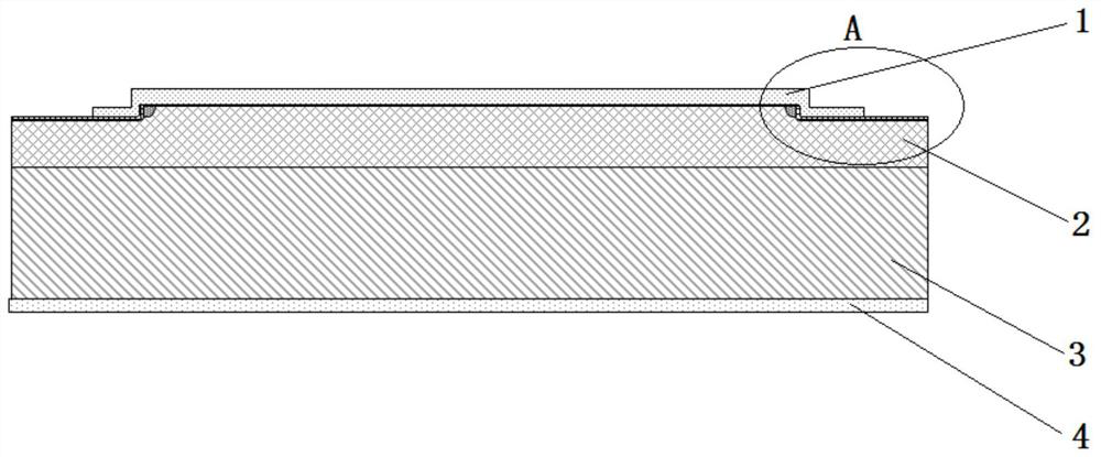
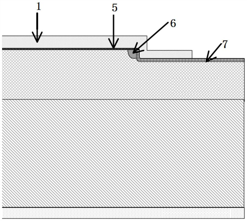
[0055] figure 1 and 2 A schematic structural diagram of an embodiment of the present invention is shown, and the structure of this embodiment is specifically shown. This embodiment relates to a Schottky manufacturing method, which is used to prepare the structure of a Schottky device. figure 1 and 2 The structure of the Schottky device prepared by this method is shown. The field limiting ring, hole self-alignment technology and LOCOS process are used to prepare, and the self-alignment of the barrier region and the field limiting ring is realized by two photolithography. Reduce the processing cost and equipment occupation, reduce the overlay requirements of the control layer and the field limit ring, especially the field limit ring structure with small line width, reduce the number of lithography layers processed, reduce the processing cost, and...


PUM

PropertyMeasurementUnit
thicknessaaaaaaaaaa
thicknessaaaaaaaaaa
electrical resistivityaaaaaaaaaa

Abstract

The present invention provides a Schottky manufacturing method, comprising the following steps: S1: depositing a layer of dielectric film on a substrate material; S2: field confinement ring photolithography and ion implantation; S3: field confinement ring area etching Etching; S4: Dielectric film stripping; S5: Metal layer deposition; S6: Metal lithography and etching. The beneficial effect of the present invention is that the field limiting ring area is etched, compared with the existing preparation process, one lithography is reduced in the process flow, the productivity is improved, the production cost is reduced, and the occupied time of the lithography machine of the manufacturing bottleneck equipment is solved.

Description

technical field [0001] The invention belongs to the technical field of semiconductor devices, and in particular relates to a Schottky manufacturing method. Background technique [0002] At present, the terminal structure of common Schottky devices is mostly the structure of field plate plus field limiting ring (single or multiple field limiting rings). The terminal structure does not contribute to the forward conduction of the device. At the same time, the Schottky of this structure The device processing process is generally a three-layer lithography structure, mainly including field limit ring lithography, dielectric layer aperture lithography, and metal layer lithography. Device manufacturing requires 3 times of lithography, which takes up the time of key equipment lithography machine. , limiting the output of the production line; the processing cost of the three-step lithography manufacturing is high, which affects the profitability of the product. SUMMARY OF THE INVENT...

Claims


Application Information

Patent Timeline
Patent Type & Authority Patents(China)
IPC IPC(8): H01L21/329
CPCH01L29/66143Y02P70/50
Inventor 王万礼宋楠陈海洋乐春林刘闯刘文彬刘晓芳徐长坡
Owner TIANJIN HUANXIN TECH DEV
Learn More