Skin anastomat nail pressing structure and skin anastomat thereof

A technology of staplers and staples, which is applied in the direction of surgical fixation nails, etc. It can solve the problems of missing staple feet, easy slippage of staples, and inability to anastomose, achieving the effects of reducing pain, reliable molding, and reducing surface roughness.

Pending Publication Date: 2019-10-18
CHANGZHOU KANGDI MEDICAL STAPLER
View PDF0 Cites 3 Cited by
  • Summary
  • Abstract
  • Description
  • Claims
  • Application Information

AI Technical Summary

Problems solved by technology

[0007] In order to solve the problems existing in the prior art that the staples are easy to slip off during the anastomosis, the legs of the staples rebound in the opposite directio...

Method used


Image

  • Skin anastomat nail pressing structure and skin anastomat thereof
  • Skin anastomat nail pressing structure and skin anastomat thereof
  • Skin anastomat nail pressing structure and skin anastomat thereof

Examples


Embodiment 1

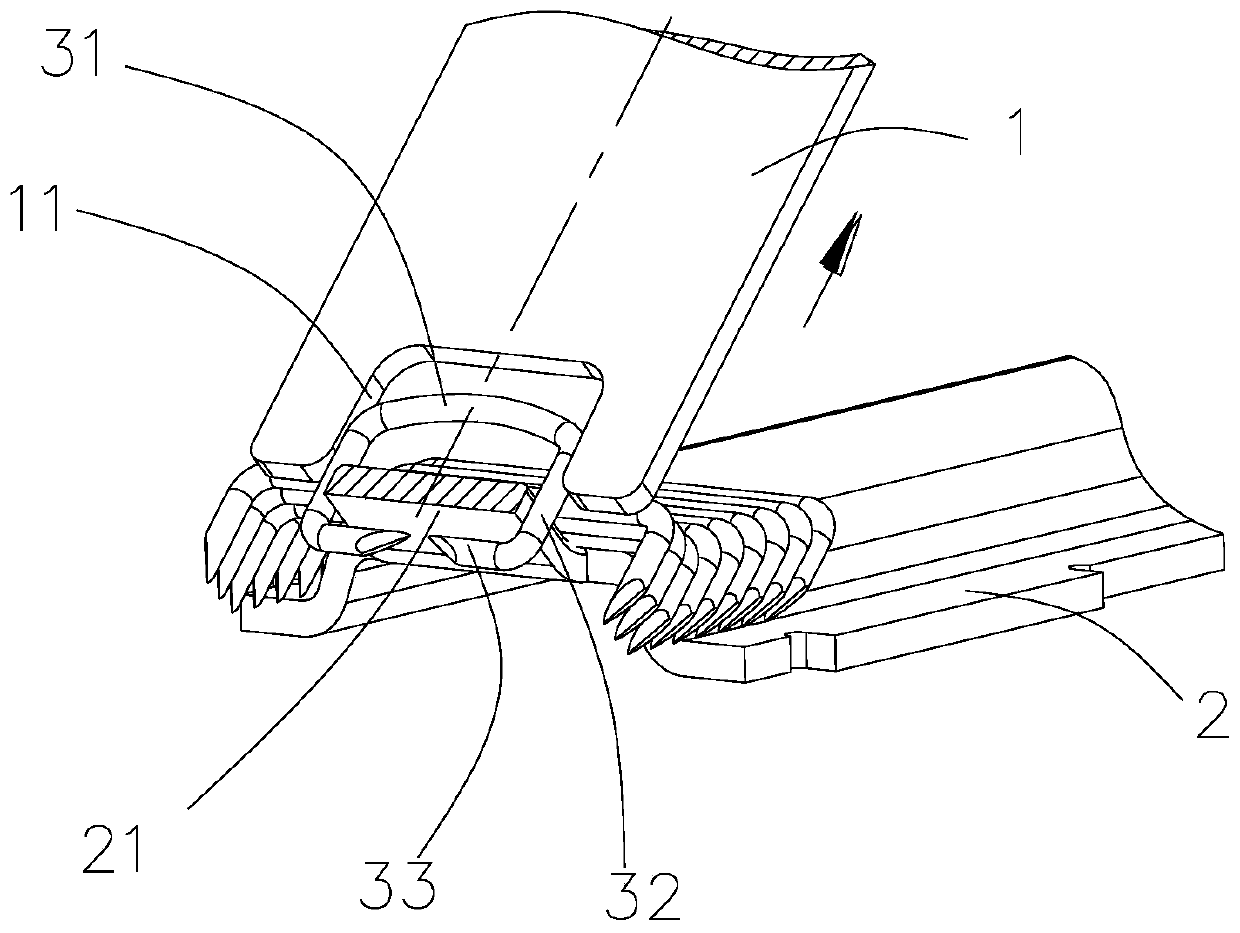
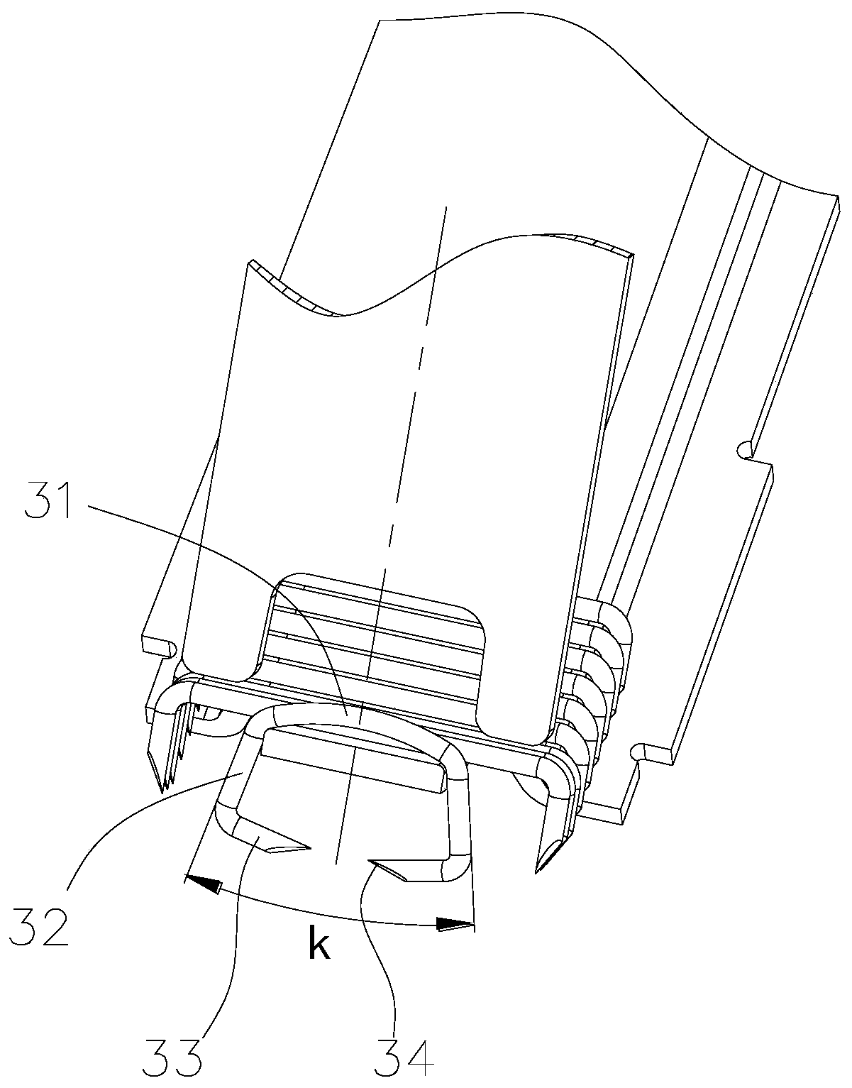
[0035] Such as Figure 4-10 As shown, a nail-pressing structure of a skin stapler includes a nail-pressing plate 4 and a nail seat 6. When operating the stapler, the direction of the arm is the rear end, and the forming end of the nail-pressing plate 4 is provided with a jaw 41 , the jaw 41 is in the shape of a bell mouth with a narrow bottom and a wide top, the opening angle of the jaw 41 is α, 0°<α<40°, and the inner sides of the jaw 41 are provided with inner profile molding surfaces 42, the end of the jaw 41 is provided with an end forming surface 43, and an arc forming surface 44 is provided between the inner profile forming surface 42 and the end forming surface 43, and an arc forming surface 44 is set on the end forming surface 43. There is a first V-shaped groove 431, and a second V-shaped groove 441 communicating with the first V-shaped groove 431 is opened on the arc forming surface 44. The bottom 45 of the jaw is provided with a pressing table 46, and the first V-sh...

Embodiment 2

[0042] Such as Figure 12 As shown, in this embodiment, the difference from Embodiment 1 is that both the first V-shaped groove 431 and the second V-shaped groove 441 are V-shaped grooves facing directly. The simplified embossing mold does not have a curved V-shaped groove, and it is obvious that the punch of such an embossing mold is easier to process and manufacture.


PUM


Abstract

The invention particularly relates to a skin anastomat nail pressing structure. The structure comprises a nail pressing plate, a nail seat and a stopper, a jaw is formed in a forming end of the nail pressing plate and is in a bell mouth shape with a wide upper side and a narrow lower side, inner stopping forming surfaces are arranged on both sides of the inside of the jaw, the end part of the jawis provided with end forming surfaces, and arc forming surfaces are disposed between the inner stopping forming surfaces and the end forming surfaces; first V-shaped grooves are formed in the end forming surfaces, second V-shaped grooves communicated with the first V-shaped grooves are formed in the arc forming surfaces, and the bottom of the jaw is provided with pressing tables; the front end ofthe nail seat is provided with a nail seat tongue part, anastomotic nails are arrayed on the nail seat, the jaw of the nail pressing plate is moved close to or away from the nail seat tongue part, andwhen the jaw cooperates with the nail seat tongue part and the anastomotic nails are formed in the jaw, the pressing tables are in contact with nail beams of the anastomotic nails. The stopper includes a stopper fixing part and a stopper head part, a door hole slidingly matched with the stopper head part is formed in the bottom of the jaw, the pressing tables are located on the two sides of the door hole, and the stopper head part is located above the nail seat tongue part.

Description

technical field [0001] The invention belongs to the technical field of skin staplers, in particular to a skin stapler structure and a skin stapler. Background technique [0002] The skin stapler is suitable for superficial skin suturing of human trauma and surgical incision, and patch fixation for abdominal hernia repair. The principle of the skin stapler is similar to that of a stapler. It has the advantages of simple operation, fast suturing speed, and good postoperative incision healing. It is the preferred medical device to replace traditional manual superficial skin suturing. Orthopedics and other departments and field rescue and other occasions. [0003] The existing skin stapler has the following defects: [0004] (1). The staples 3 of the skin stapler are mostly made of stainless steel wires with a diameter of 0.5-0.8 mm, and the staples 3 with a diameter of 0.6 mm are more commonly used. The staples 3 are arranged in large numbers inside the stapler The nail pres...

Claims


Application Information

Patent Timeline
IPC IPC(8): A61B17/068
CPCA61B17/0682
Inventor 杨卫民王海涛冷小军
Owner CHANGZHOU KANGDI MEDICAL STAPLER
Why Eureka
Try Eureka