Eureka AIR delivers breakthrough ideas for toughest innovation challenges, trusted by R&D personnel around the world.

Building waste screening device

A technology for screening equipment and construction waste, which is used in solid separation, separation of solids from solids by air flow, chemical instruments and methods, etc. It can improve the efficiency of air separation, the screening effect is good, and the equipment load can be reduced.

Inactive Publication Date: 2019-10-18
长兴睿锋科技有限公司
View PDF2 Cites 3 Cited by
  • Summary
  • Abstract
  • Description
  • Claims
  • Application Information

AI Technical Summary

Problems solved by technology

The problems in the screening work are as follows: First, the drum is a relay type during screening, that is, the material to be screened must fall directly on the drum to realize the diversion effect, and the material that does not fall on the drum cannot be realized. Screening will affect the screening effect; second, the drum will collide with the material for a long time, and the service life is short; third, because the drum must be located "below the sprinkling end of the belt conveyor and on the falling track of the sprinkling material" to achieve the diversion effect, so the sprinkling The angle of the device and the wind device must also be relatively fixed, and the adaptability of the equipment is not strong; in addition, this kind of waste treatment and screening device is mainly used to deal with domestic waste, and the screening process will be accompanied by a large number of Dust, the equipment cannot realize the recovery and treatment of dust

Method used


Image

  • Building waste screening device
  • Building waste screening device
  • Building waste screening device

Examples


Embodiment Construction

[0020] The present invention will be further described below through specific embodiments.

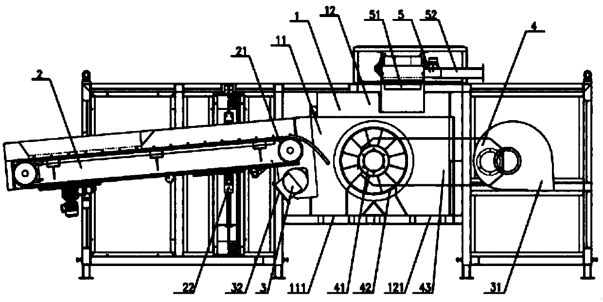
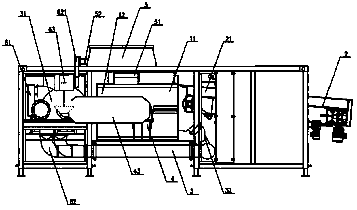
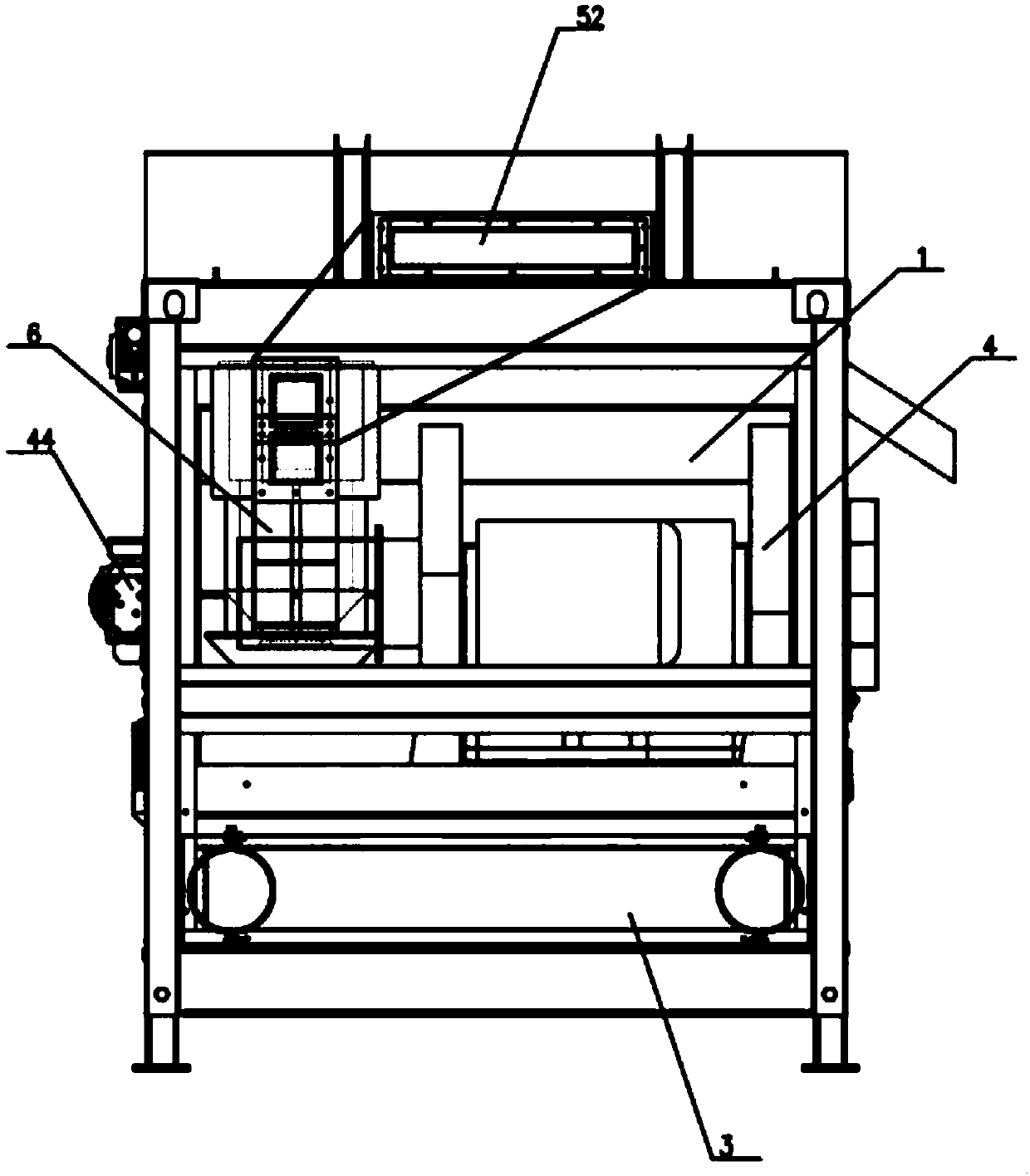
[0021] refer to Figure 1 to Figure 6 As shown, a construction waste screening equipment includes a sorting chamber 1, a throwing device 2, a wind device 3, a medium and heavy object sorting device 4, a light and heavy material sorting device 5, and a dust removal device 6;

[0022] The separation chamber 1 has a first separation zone 11 and a second separation zone 12, the first separation zone 11 has a heavy material outlet 111 at the lower end, and the second separation zone 12 has a medium and heavy material outlet 121 at the lower end;

[0023] The throwing device 2 includes a belt conveyor 21 and a position adjustment mechanism 22. One end of the belt conveyor 21 leads into the winnowing chamber 1 to transport materials to the first separation zone 11. The position adjustment mechanism 22 is a driving mechanism arranged under the belt conveyor 21. Cylinder, adjust the relative p...


PUM


Abstract

The invention relates to the field of building waste recycling, in particular to a building waste screening device which comprises a sorting chamber, a throwing device, a wind force device and a medium-heavy object sorting device. A first separation zone and a second separation zone are arranged in the sorting chamber; the throwing device is used for conveying materials to the first separation zone; the wind force device utilizes a wind force for raising the materials thrown out from the first separation zone; and the medium-heavy object sorting device comprises a double-layer sorting cylinder, a negative pressure mechanism, a fan and a cylinder drive mechanism. The building waste screening device can be used for separating building wastes into heavy substances, medium-heavy substances andlight substances according to the needs so as to have a good screening effect; the heavy substances cannot collide with the double-layer sorting cylinder in the screening process, so that the servicelife of the double-layer sorting cylinder is prolonged; in the screening process, a material throwing angle and a material throwing force of the throwing device can be adjusted according to the needs, so that an adaptive capacity of the equipment is greatly improved; and by using the building waste screening device, an equipment load can be effectively reduced, and the winnowing efficiency is improved.

Description

technical field [0001] The invention relates to the field of construction waste recycling, in particular to construction waste screening equipment and a screening method. Background technique [0002] Construction waste refers to the waste generated during the construction, repair and demolition of buildings, including sand, bricks, concrete blocks, waste wood, glass, asbestos, paper scraps, waste plastics, metals and others. At present, my country's annual construction waste is about 1.55 billion tons. A large amount of construction waste not only seriously affects people's lives, but also hinders the development of cities. The construction waste that can be used as a resource is about 800 million tons. The existing domestic construction waste recycling method is a production process that rationally combines different crushing equipment, screening equipment, transmission equipment and equipment for removing impurities, such as a construction waste treatment disclosed in the...

Claims


Application Information

Patent Timeline
IPC IPC(8): B07B9/02B07B7/01B07B11/06B07B11/02
CPCB07B7/01B07B9/02B07B11/02B07B11/06
Inventor 不公告发明人
Owner 长兴睿锋科技有限公司
Why Eureka
Eureka Blog
Learn More