
Shredded paper separator and shredded paper separation method thereof

A technology of separator and paper shredding, which is applied in the direction of chemical instruments and methods, solid separation, and separation of solids from solids with airflow, which can solve the problems of polluting indoor environment, dust pollution, increasing fire hazards, etc.

Pending Publication Date: 2019-10-18
深圳市东鹏科技发展有限公司
View PDF0 Cites 1 Cited by
  • Summary
  • Abstract
  • Description
  • Claims
  • Application Information

AI Technical Summary

Problems solved by technology

These leftovers are piled up in the production workshop. If they are not removed in time, they will not only pollute the indoor environment, affect production, but also increase fire hazards, which is a major hidden danger that threatens production and safety.
The traditional processing procedures of most printing companies in China are still collecting these waste papers by manual waste paper boxes, or sending them to the waste paper stacking room through positive pressure pipes; Dust pollution is serious, and there are relatively large dust explosion and fire hazards; in addition, if the processing of these waste papers involves confidential products, it needs to be crushed before processing, and a separate crushing workshop needs to be set up for special operation

Method used


Image

  • Shredded paper separator and shredded paper separation method thereof
  • Shredded paper separator and shredded paper separation method thereof
  • Shredded paper separator and shredded paper separation method thereof

Examples


Embodiment Construction

[0028] The following will clearly and completely describe the technical solutions in the embodiments of the present invention with reference to the accompanying drawings in the embodiments of the present invention. Obviously, the described embodiments are only some, not all, embodiments of the present invention. Based on the embodiments of the present invention, all other embodiments obtained by persons of ordinary skill in the art without making creative efforts belong to the protection scope of the present invention.

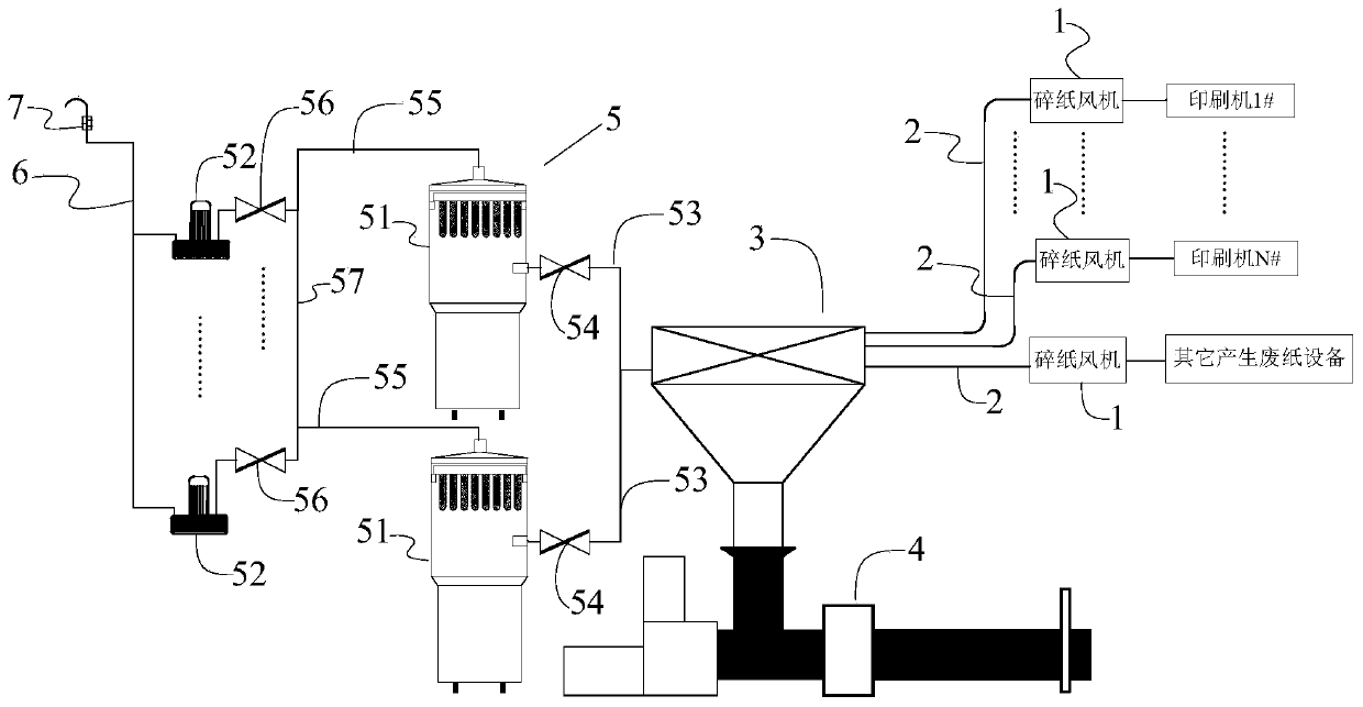
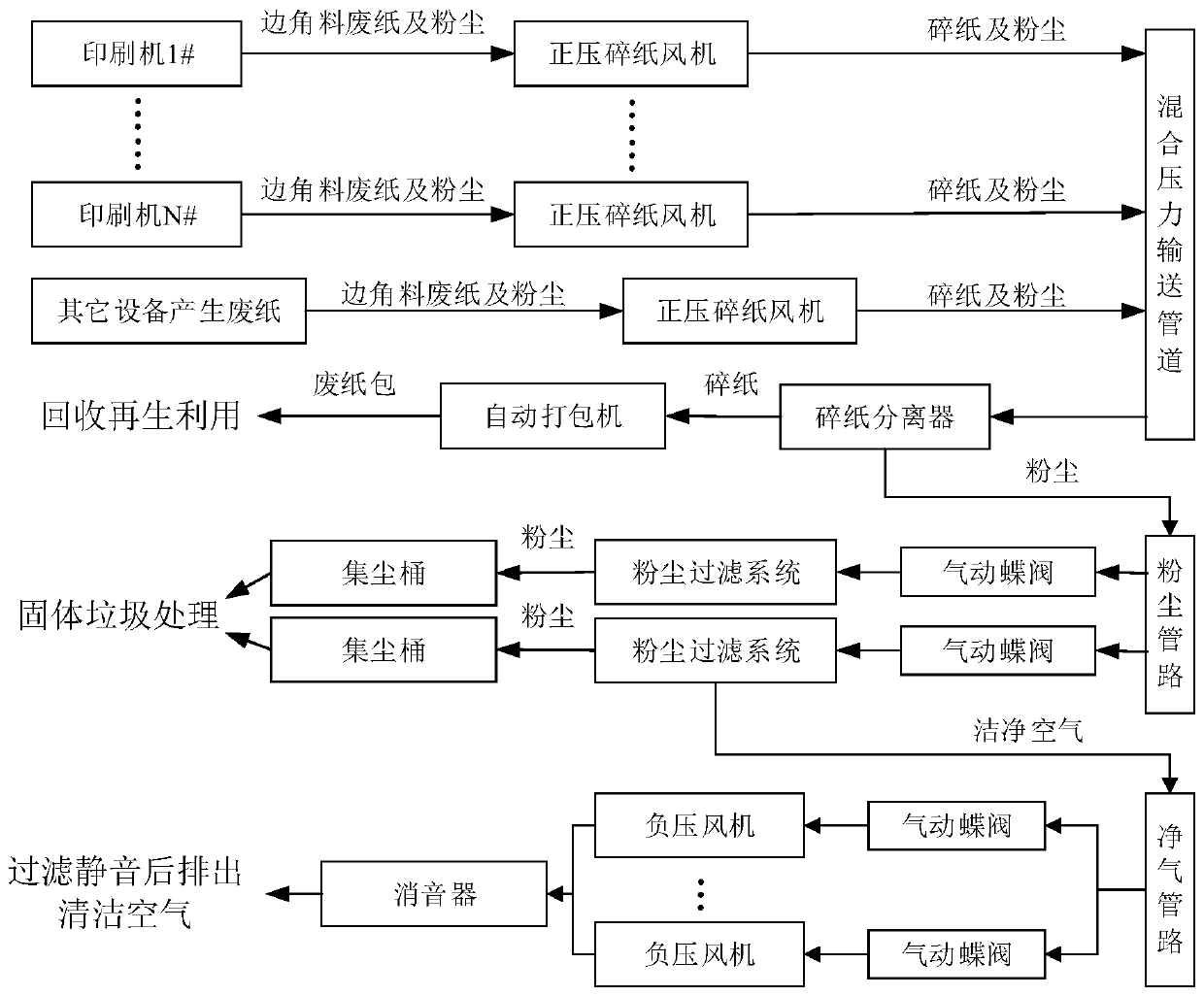
[0029] See Figure 1 to Figure 6, the waste paper collection system of the present embodiment includes a shredder fan 1, a mixed pressure shredded paper conveying pipeline 2, a shredded paper separator 3, a shredded paper baler 4 and a negative pressure dust removal system 5; the waste paper of the shredded paper fan 1 The paper input end communicates with the waste paper output end of the waste paper equipment, and the shredded paper output end of the shreddi...


PUM


Abstract

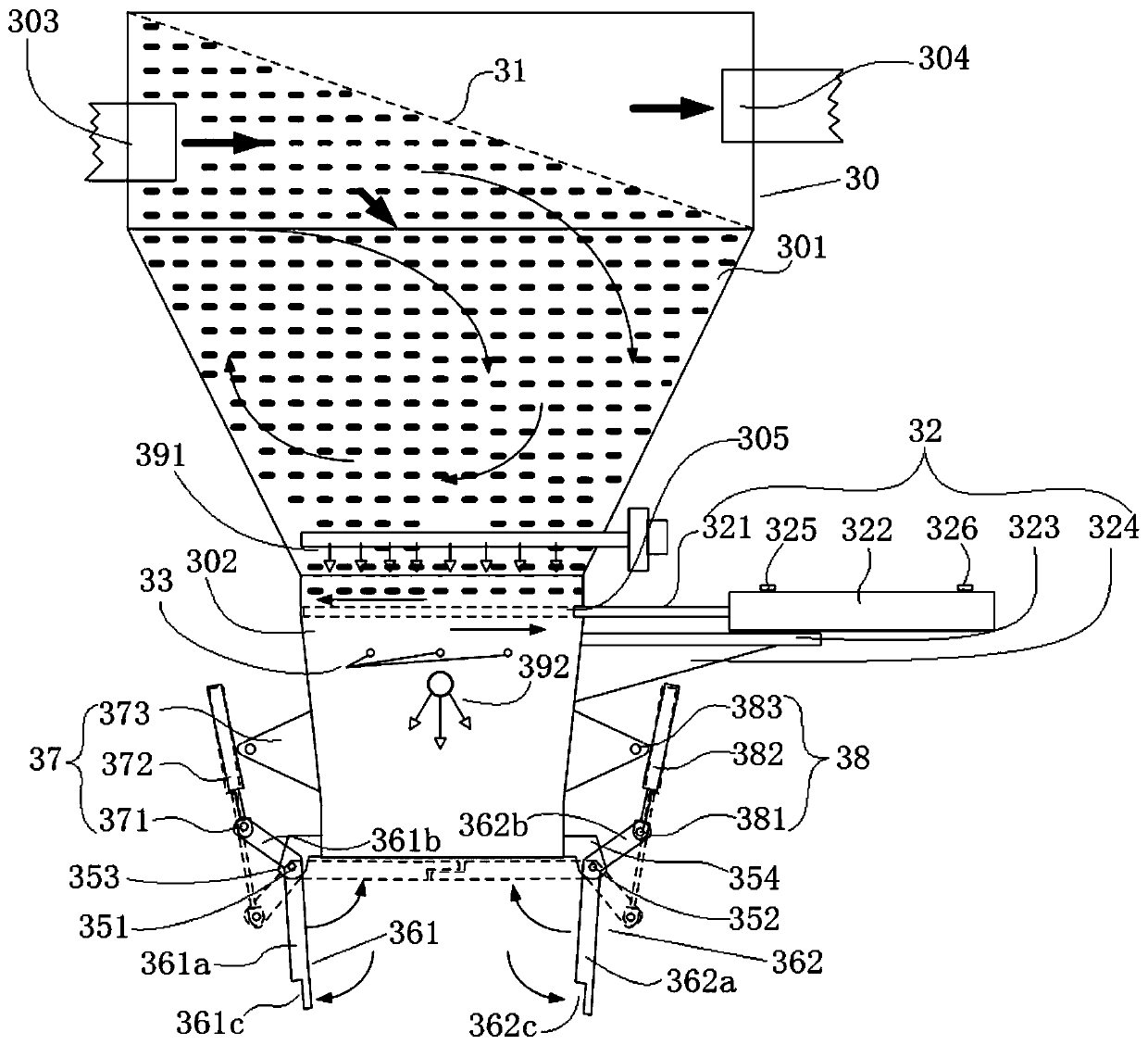
The invention discloses a shredded paper separator. The shredded paper separator comprises a shredded paper separation bin, a filter net, a bin fullness detection unit, an upper and lower bin divisionand combination mechanism, a bin door and a bin door driving device, wherein the shredded paper separation bin comprises an upper bin and a lower bin; the filter net is arranged on the upper end of the shredded paper separation bin; the bin fullness detection unit is arranged at the upper end of the lower bin; the upper and lower bin division and combination mechanism is movably inserted in the interior of the shredded paper separation bin; the bin door is arranged at a lower bin opening of the shredded paper separation bin; the bin door driving device is used for driving the bin door to openand close; the bin fullness detection unit, the upper and lower bin division and combination mechanism and the bin door driving device are electrically connected to a waste paper collecting control device of a waste paper collecting system; a shredded paper input end communicating with a shredded paper output end of a shredded paper draught fan of the waste paper collecting system is arranged onthe upper end of the shredded paper separation bin and is located at a position below the filter net; and a dust output end communicating with a dust input end of a negative pressure moisture-proof system of the waste paper collection system is arranged on the upper end of the shredded paper separation bin and is located at a position above the filter net.

Description

technical field [0001] The invention relates to a shredded paper separator and a shredded paper separation method thereof. Background technique [0002] With the progress of society and the development of industrial economy, more and more attention has been paid to the environmental protection of industrial production, energy saving and emission reduction. For modern enterprises, a clean production environment is a must. Timely and effective disposal of waste products and materials generated in the production process is particularly important; the products of the printing factory are mainly printed materials such as bills, books, and magazines. The waste generated during the production of these products is mainly paper trim, shredded paper and paper dust. These leftovers are piled up in the production workshop. If they are not removed in time, they will not only pollute the indoor environment, affect production, but also increase fire hazards, which is a major hidden danger...

Claims


Application Information

Patent Timeline
IPC IPC(8): B30B9/30B07B7/06
CPCB30B9/30B30B9/301B30B9/3035B07B7/06
Inventor 代楠邱小玮蔡冀红罗维广姚金成严振业王军玲
Owner 深圳市东鹏科技发展有限公司
Learn More