Blockage removing pipeline and blockage removing method for double-sleeve long-distance pneumatic material conveying

A pneumatic conveying and long-distance technology, which is applied in the direction of conveying bulk materials, conveyors, transportation and packaging, etc., can solve the problems of high investment and annual operating costs, a large number of air compressors, and poor economy, so as to avoid the waste of compressed air , high degree of automation and short blowing time

Pending Publication Date: 2019-10-18
NORTHWEST ELECTRIC POWER DESIGN INST OF CHINA POWER ENG CONSULTING GROUP
View PDF0 Cites 5 Cited by
  • Summary
  • Abstract
  • Description
  • Claims
  • Application Information

AI Technical Summary

Problems solved by technology

[0002] At present, the technology of long-distance pneumatic conveying of granular materials at home and abroad is relatively mature for the environment with only horizontal conveying and a single ascending section. When this kind of pneumatic conveying pipeline is arranged, it usually can only avoid pipeline clogging by mixing air and blowing it in the whole process. The traditional treatment method requires a large number of air compressors and consumes a lot of air, which requires investment and annual operation. The cost is high and the economy is poor

Method used


Image

  • Blockage removing pipeline and blockage removing method for double-sleeve long-distance pneumatic material conveying

Examples


Embodiment Construction

[0026] The present invention will be further described in detail below in conjunction with the accompanying drawings and embodiments.

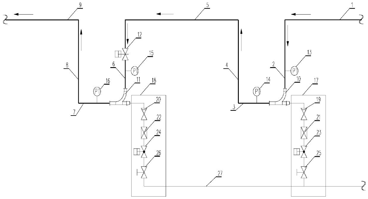
[0027] see figure 1 , taking two groups of U-shaped pipeline segments as an example, the anti-blocking pipeline for long-distance pneumatic conveying of materials with double sleeves in the present invention includes a first wear-resistant tee joint 10, a second wear-resistant tee joint 11 and a first wear-resistant tee joint 11. The pressure transmitter 13, the second pressure transmitter 14, the third pressure transmitter 15, the fourth pressure transmitter 16, the first horizontal section 1 of the first U-shaped arrangement of the long-distance double-pipe conveying material pipeline and the third horizontal section 5 through the first descending section 2, the second horizontal section 3 and the first ascending section 4; the third horizontal section 5 and the second U-shaped arrangement of the long-distance double casing conveying materia...


PUM


Abstract

The invention provides a blockage removing pipeline and a blockage removing method for double-sleeve long-distance pneumatic material conveying. The blockage removing pipeline comprise a plurality ofsets of U-shaped pipeline sections, and an ascending section and a descending section of a long-distance pneumatic material conveying pipeline are distributed on the U-shaped pipeline sections; the U-shaped pipeline sections are connected through a plurality of horizontal pipeline sections in a sectional mode; each U-shaped pipeline sections is sequentially composed of the descending section, thehorizontal section and the ascending section according to a material conveying direction of the pipeline, pipelines at the joints between descending sections and horizontal sections are connected withblockage removing pipeline valve group through wear-resistant T-joints, pressure transmitters are arranged on the descending section pipelines and the horizontal section pipelines, and each blockageremoving pipeline valve group comprises a check valve, a regulating valve, a pneumatic shut-off valve and a manual shut-off valve which are sequentially arranged between the wear-resistant T-joint anda compressed air pipeline. The blockage removing method is simple and convenient to operate, can accurately locate the position where the blockage occurs, and can quickly and effectively remove the blockage when a plurality of descending sections are blocked at the same time.

Description

technical field [0001] The invention belongs to the field of gas-solid two-phase flow transportation, and in particular relates to a pipeline and a method for eliminating clogging of materials for long-distance pneumatic conveying of materials with double casings, and is especially suitable for flying in thermal power plants or coal-fired boiler power stations and power workshops. For the long-distance transportation of granular materials such as ash, grain, and cement, it is necessary to arrange pneumatic conveying pipelines under the conditions of large undulations, across railways, highways, through culverts, and rivers. Background technique [0002] At present, the technology of long-distance pneumatic conveying of granular materials at home and abroad is relatively mature for the environment with only horizontal conveying and a single ascending section. When this kind of pneumatic conveying pipeline is arranged, it usually can only avoid pipeline clogging by mixing air ...

Claims


Application Information

Patent Timeline
Patent Type & Authority Applications(China)
IPC IPC(8): B65G53/16B65G53/52B65G53/66B65G53/34B65G53/46
CPCB65G53/16B65G53/34B65G53/46B65G53/52B65G53/66
Inventor 毕宁王浩康爱军李鹏贾晓慧薛靖霞
Owner NORTHWEST ELECTRIC POWER DESIGN INST OF CHINA POWER ENG CONSULTING GROUP
Why Eureka
Try Eureka