Method for erecting T-shaped beam by using small-sized machinery

A mechanical and small-scale technology, which is applied in the direction of erecting/assembling bridges, bridges, bridge construction, etc., can solve the problems of difficult erection of T-beams, high construction difficulty, and high construction risk, and achieve easy operation, low construction difficulty, and simple assembly Effect

Active Publication Date: 2019-10-18
CHINA RAILWAY 23RD BUREAU GRP THIRD ENG CO LTD
View PDF5 Cites 0 Cited by
  • Summary
  • Abstract
  • Description
  • Claims
  • Application Information

AI Technical Summary

Problems solved by technology

[0015] The purpose of the present invention is to overcome the problems existing in the prior art that when the bridge erecting machine, T-beam or crane cannot enter the construction site, the erection of the T-beam is difficult, the construction is difficult, the construction cost is high and the construction risk is high, providing A method of erecting T-beams using small machines. Small machines are produced on site, and are simple to assemble, easy to install, easy to operate, and have special support devices. On the premise of safety, the erection of T-beams can be completed simply and conveniently. operations to reduce construction difficulty, construction cost and construction safety hazards

Method used


Image

  • Method for erecting T-shaped beam by using small-sized machinery
  • Method for erecting T-shaped beam by using small-sized machinery
  • Method for erecting T-shaped beam by using small-sized machinery

Examples


Embodiment 1

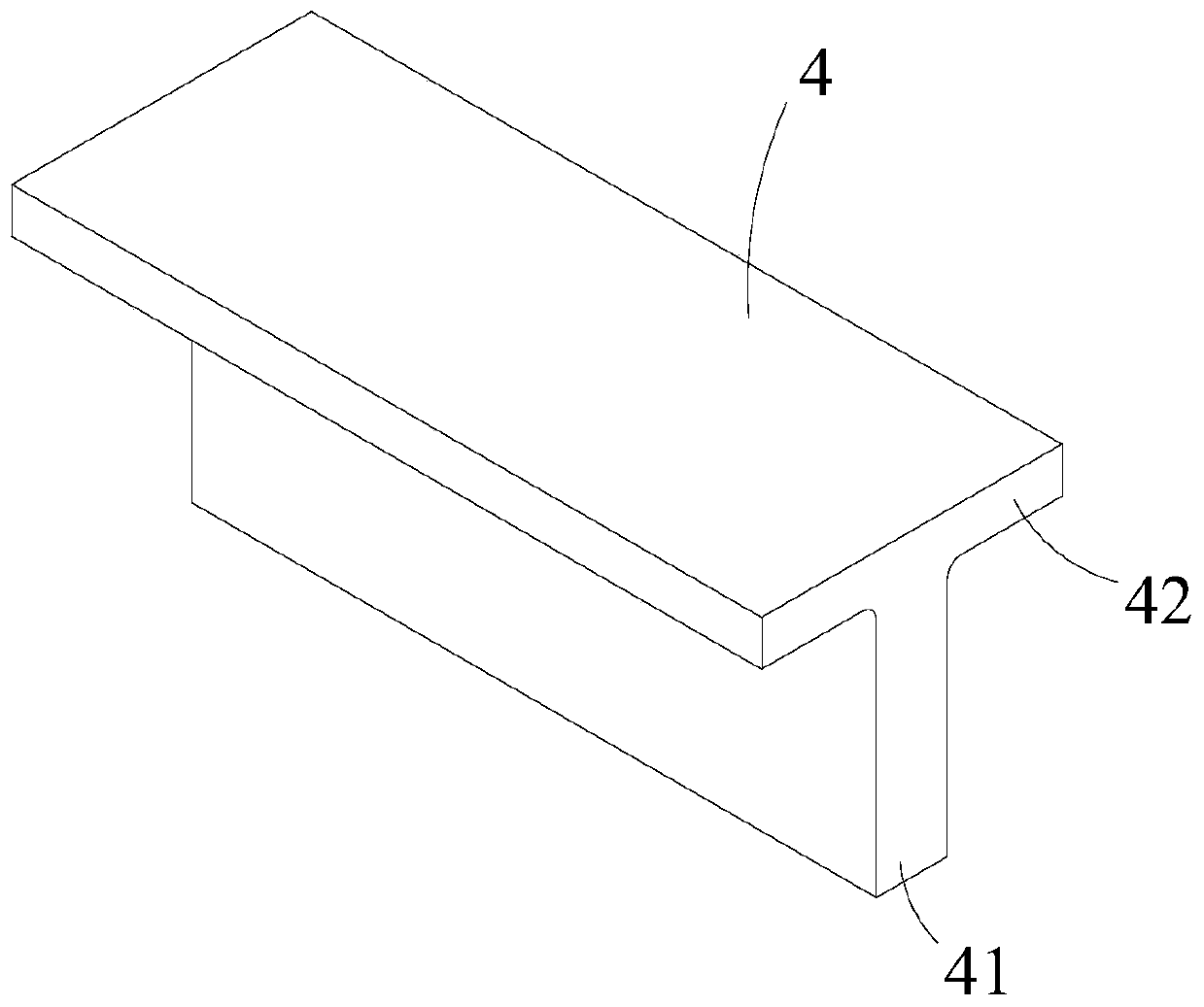
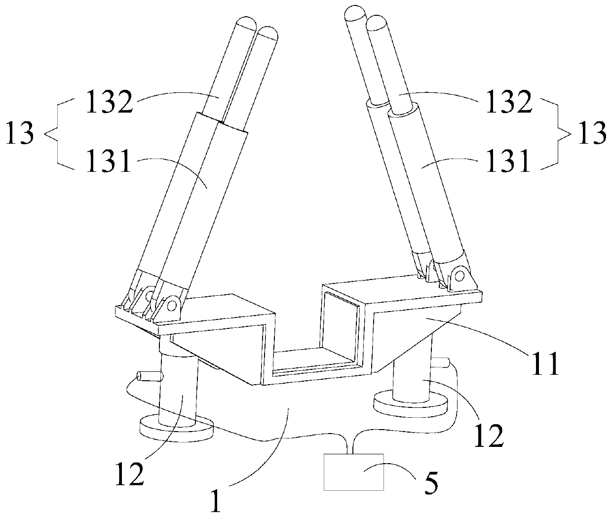
[0110] Such as figure 1 , 2 Shown in and 3, a kind of method of using small-sized mechanical erection T-beam 4 of the present invention, comprises the following steps:

[0111] Step 1, making the jacking device 1 and the moving device 2 at the construction site, wherein,

[0112] The jacking device 1 is used for jacking the T-beam 4, and the jacking device 1 includes a first bracket 11, a jacking assembly 12 and a first support rod 13, and the first bracket 11 is connected to the first bracket respectively. The bracket 11 is detachably connected to the first support rod 13, the first bracket 11 is used to vertically support the T-beam 4, and the first support rod 13 is used to laterally support the T-beam 4. The jacking assembly 12 is used to vertically push the first bracket 11;

[0113] The moving device 2 is used to move the T-beam 4, the moving device 2 includes a second support 21, a moving assembly 22 and a second support rod 23, and the second support 21 is connected...

Embodiment 2

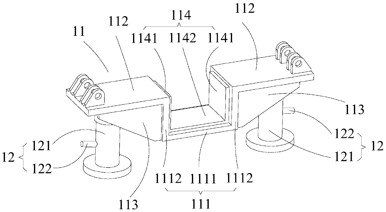
[0142] Such as figure 1 , 2 As shown in and 3, a method for erecting a T-beam 4 using a small machine as described in Embodiment 1, the first bracket 11 includes a first support portion 111 and a first support 112, and the first support portion 111 is connected with the first support 112, the first support part 111 is used to support the T-beam 4, the first support 112 is two, respectively set on the first support part 111 On both sides of each of the first supports 112, the first support rod 13 is hinged.

[0143] On the basis of the above, in a further preferred manner, the first support part 111 includes a first bottom support part 1111 and two first side support parts 1112, and the first side support parts 1112 are respectively arranged on the first bottom On both sides of the support part 1111, the first side support part 1112 is connected to the first bottom support part 1111, the first bottom support part 1111 is used to support the bottom surface of the web 41, and t...

Embodiment 3

[0156] Such as figure 1 , 2 Shown in and 3, as described in embodiment 1 or 2, a kind of method that uses small-sized machinery to erect T-beam 4,

[0157] On the basis of the above, in a further preferred manner, the second bracket 21 includes a second support part 211, and a second support part 211 connected to the second support part 211 is provided on both sides of the second support part 211. Supports 212 , the second support portion 211 is used to support the T-beam 4 , and the second support rod 23 is hinged on each second support 212 .

[0158] On the basis of the above, in a further preferred manner, the second support part 211 includes a second bottom support part 2111 and two second side support parts 2112, and the second side support parts 2112 are respectively arranged on the second bottom On both sides of the support part 2111, the second side support part 2112 is connected to the second bottom support part 2111, and the second bottom support part 2111 is used ...


PUM


Abstract

The invention relates to the bridge T-shaped beam construction field, especially a method for erecting T-shaped beam by using small-sized machinery. The method comprises following steps: step 1, a jacking device and a moving device are manufactured; step 2, the jacking device is installed; step 3, the moving device is installed; step 4, the T-shaped beam is moved; step 5, the T-shaped beam is erected. By using the method provided by the invention, when a bridge girder erection machine, a T-shaped beam, or a crane cannot enter the construction site, the jacking device and a translating device can be used to erect the T-shaped beam, and can be manufactured on site, and in addition, assembly is simple, installation is convenient, and operation is easy. A special supporting device is provided,and under a precondition of guaranteeing the safety performance, the erection operation of the T-shaped beam can be completed simply and conveniently, and therefore construction difficulty, construction costs and construction safety hidden troubles are reduced.

Description

technical field [0001] The invention relates to the field of bridge T-beam construction, in particular to a method for erecting T-beams using small machines. Background technique [0002] At present, T-beams are generally used in the laying of bridges. The reason is that the T-beams are equivalent to digging out the concrete in the tensile area of ​​the rectangular beams that does not play a role in the flexural strength. It is completely different from the original rectangular flexural strength. In addition to the same, it can not only save concrete, but also reduce the self-weight of components, and improve the spanning ability. [0003] Such as figure 1 As shown, the protruding parts on both sides of the T-beam 4 are called flanges 42 , and the middle parts are called webs 41 . [0004] For the erection of T-beams, because the single-piece T-beams used as bridges are very heavy, quantitative production of beam yards and bridge erecting machines are usually used for erec...

Claims


Application Information

Patent Timeline
Patent Type & Authority Applications(China)
IPC IPC(8): E01D21/00
CPCE01D21/00
Inventor 冷福祥尹智勇陈文萍刘咏梅熊志刚羊有彬李松周琪马敏
Owner CHINA RAILWAY 23RD BUREAU GRP THIRD ENG CO LTD
Why Eureka
Try Eureka