Lifting hydraulic oil cylinder buffering structure of garbage transfer truck

The technology of a garbage transfer vehicle and hydraulic cylinder is applied in the field of hydraulic machinery to achieve the effects of stable and reliable working performance, simplified structure, and simple buffer structure

Pending Publication Date: 2019-10-18
四川优机实业股份有限公司
View PDF0 Cites 3 Cited by
  • Summary
  • Abstract
  • Description
  • Claims
  • Application Information

AI Technical Summary

Problems solved by technology

[0003] The technical problem to be solved by the present invention is to provide a buffer structure for lifting hydraulic cylinders of garbage transfer vehicles to overcome the drawbacks of the current buffer cylinders, which are complex in structure and expensive

Method used


Image

  • Lifting hydraulic oil cylinder buffering structure of garbage transfer truck
  • Lifting hydraulic oil cylinder buffering structure of garbage transfer truck
  • Lifting hydraulic oil cylinder buffering structure of garbage transfer truck

Examples


Embodiment approach

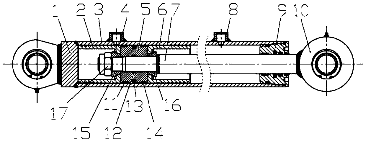
[0033] To further facilitate processing and assembly, the end of the piston rod 7 connected to the piston 5 is provided with a positioning step surface, and the end of the piston rod 7 is connected with a lock nut 17; both the piston 5 and the buffer piston have holes for the piston rod 7 to pass through. The piston 5 and the buffer piston are fixedly installed between the positioning step surface and the lock nut 17 through the lock nut 17; a piston bush is provided between the inner hole of the buffer piston and the outer wall of the piston rod 7. The inner diameter of the piston bushing is matched with the outer diameter of the piston rod 7 at the corresponding position, and the outer diameter of the piston bushing is matched with the inner hole diameter of the buffer piston at the corresponding position; for the same group of buffer pistons, only need to replace different specifications Piston bushings can be applied to piston rods 7 with different outer diameter specificati...


PUM


Abstract

The invention relates to a lifting hydraulic oil cylinder buffering structure of a garbage transfer truck, and belongs to the technical field of hydraulic machinery. The lifting hydraulic oil cylinderbuffering structure is characterized in that buffering pistons are additionally arranged in a cylinder body, grooves which are distributed in a spiral mode are formed in the outer circle surfaces ofthe buffering pistons, and the sectional areas of the grooves are designed in a gradual changing mode in the axis direction of the grooves; the adjustment of the flow of oil liquid can be automatically realized through changes of the relative positions between the spiral grooves of the buffering pistons and oil ports so as to achieve the buffering function; and the buffering piston located on oneside of a rodless cavity plays a role in buffering in the working starting stage of an oil cylinder, and the buffering piston located on the side of a rod cavity plays a role in buffering at the working end stage of the oil cylinder. According to the lifting hydraulic oil cylinder buffering structure of the garbage transfer truck, the buffering structure of the oil cylinder is simple, convenient to machine and low in cost, the buffering function of the oil cylinder can be realized without additionally arranging a buffering device, meanwhile, the function of meeting different requirements of the buffering speed can be realized according to different machining parameters, and the working performance is stable and reliable.

Description

Technical field [0001] The invention relates to a buffer structure of a lifting hydraulic cylinder of a garbage transfer vehicle, and belongs to the technical field of hydraulic machinery. Background technique [0002] At present, the main structure of a well-known hydraulic cylinder is composed of a cylinder tube, a cylinder bottom, an oil port, a piston, a piston rod, a guide sleeve, and so on. The piston divides the cylinder into two oil chambers with a rod cavity and a rodless cavity, and the reciprocating movement of the piston rod is realized by pushing the piston by the oil. At present, the lifting hydraulic cylinder of the garbage transfer vehicle is required by the nature of the work, that is, it is required to be smooth and slow during the initial and end stages of lifting the garbage can to avoid impact and cause garbage tossing, and the cylinder with a buffer function is used. At present, the main method to realize the buffer function is to add a buffer device. The m...

Claims


Application Information

Patent Timeline
IPC IPC(8): F15B15/22F15B15/14F16J1/12F16J7/00
CPCF15B15/227F15B15/224F15B15/1452F15B15/1447F15B15/1457
Inventor 白伟
Owner 四川优机实业股份有限公司
Why Eureka
Try Eureka