Cylinder buffer device and operating method for hydraulic hoist
A buffer device and hydraulic oil technology, applied in the direction of fluid pressure actuating device, etc., can solve the problems of affecting the service life of sealing components and hydraulic system, reducing the stability and reliability of the buffer device, and high-pressure oil hindering the effect. The effect of high reliability, no pressure loss, and simple manufacturing process
- Summary
- Abstract
- Description
- Claims
- Application Information
AI Technical Summary
Problems solved by technology
Method used
Image
Examples
Embodiment 1
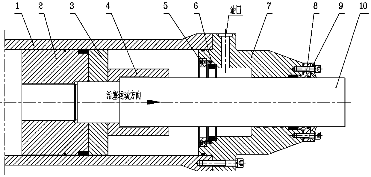
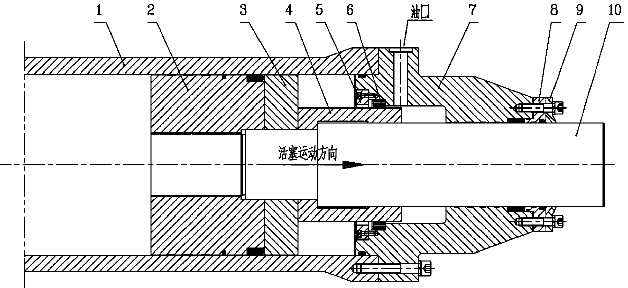
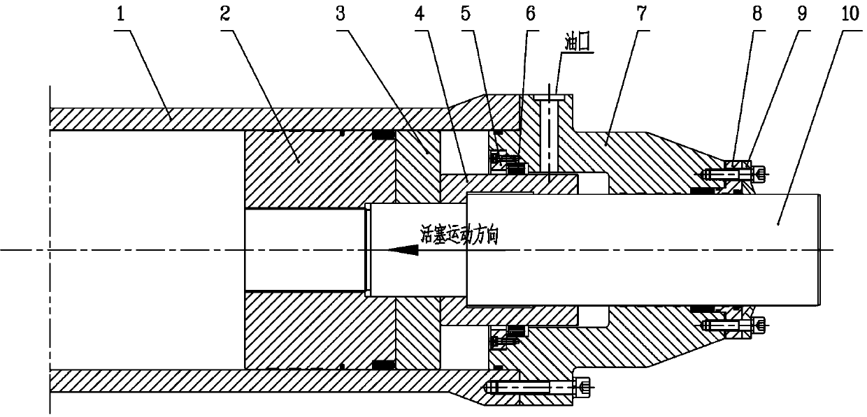
[0028] Such as Figure 1-5 , a hydraulic hoist oil cylinder buffer device, which includes a cylinder body 1, a load-bearing piston 2 is installed in sliding fit inside the cylinder body 1, a piston rod 10 is fixedly installed inside the load-bearing piston 2, and the piston rod 10 One end inside the cylinder body 1 is fixed with a half piston 3 and a buffer sleeve 4, and one end of the cylinder body 1 is equipped with a lower cover 7, and the end of the lower cover 7 located inside the cylinder body 1 is processed with an annular groove. A throttling orifice 6 is installed inside the groove, and the throttling orifice 6 is sealed inside the annular groove through a gland 5. A sealing gland 8 and a scraper ring 9 are installed on the outer end surface of the lower cover 7. The sealing The gland 8 and the scraping ring 9 cooperate with the outer wall of the piston rod 10 .
[0029] Further, the groove width of the inner annular groove of the lower cover 7 is greater than the th...
Embodiment 2
[0035] Such as figure 1 , before the start of buffering, the buffer sleeve 4 moves quickly with the piston rod 10. At this time, the buffer sleeve 4 is located inside the cylinder body 1 without any damping and buffering effect, and the hydraulic oil pushes the piston rod 10 to move quickly, so that the fast gate can fall quickly , to quickly close the water flow; thereby ensuring the purpose of fast closing.
Embodiment 3
[0037] Such as figure 2 , in the buffer stage, when the fast gate reaches the end of the stroke and is about to reach the bottom sill of the gate, the right end of the buffer sleeve 4 is first inserted into the throttle orifice 6, and the flow cross-sectional area of the hydraulic oil decreases instantly, and the left side of the throttle orifice 6 The pressure of the hydraulic oil increases, pushing the throttle orifice 6 to move to the right, and pressing the throttle orifice 6 tightly on the step of the lower cover 7, so that the 16 annular through holes uniformly distributed on the throttle orifice 6 are in the In the closed state, the hydraulic oil can only flow to the oil tank through the annular gap formed by the outer diameter of the buffer sleeve 4 and the inner diameter of the throttle orifice 6, which plays the role of throttling through the annular gap, so that the speed of the fast door is rapidly reduced, and finally falls smoothly. On the bottom sill of the g...
PUM
 Abstract
Description
Claims
Application Information
 - R&D
- Intellectual Property
- Life Sciences
- Materials
- Tech Scout
- Unparalleled Data Quality
- Higher Quality Content
- 60% Fewer Hallucinations
Browse by: Latest US Patents, China's latest patents, Technical Efficacy Thesaurus, Application Domain, Technology Topic, Popular Technical Reports.
© 2025 PatSnap. All rights reserved.Legal|Privacy policy|Modern Slavery Act Transparency Statement|Sitemap|About US| Contact US: help@patsnap.com


