
Liquid crystal display panel driving method, driving circuit and display device

A technology of a liquid crystal display panel and a driving method is applied in the field of driving circuits, display devices, and driving methods of liquid crystal display panels, and can solve the problem of long charging and discharging time for liquid crystal capacitor plate voltage changes, high dynamic power consumption of circuit systems, and display panel color. The problem of low gamut can be improved to improve the charging quality, increase the lighting time, and improve the color gamut.

Active Publication Date: 2022-07-05
BOE TECH GRP CO LTD
View PDF11 Cites 0 Cited by
  • Summary
  • Abstract
  • Description
  • Claims
  • Application Information

AI Technical Summary

Problems solved by technology

[0002] In the liquid crystal display panel of the related art, a higher driving voltage is required to drive the liquid crystal to flip. Since the data voltage transmitted on the data line cannot meet the requirements of the driving voltage, it is necessary to use a public voltage signal flipping method to increase the driving voltage. The inversion frequency of the voltage signal is the frame frequency. Due to the polarity inversion of adjacent frames, the voltage of the liquid crystal capacitor plate will change greatly, resulting in a longer charge and discharge time, which compresses the lighting time, resulting in a lower color gamut of the liquid crystal display panel. Moreover, the inversion of the common voltage signal will lead to high dynamic power consumption of the circuit system, and will also cause EMI (Electro Magnetic Interference, electromagnetic interference) to other electrical signals.

Method used


Image

  • Liquid crystal display panel driving method, driving circuit and display device
  • Liquid crystal display panel driving method, driving circuit and display device
  • Liquid crystal display panel driving method, driving circuit and display device

Examples


Embodiment Construction

[0026] In order to make the technical problems, technical solutions and advantages to be solved by the embodiments of the present invention clearer, the following detailed description will be given in conjunction with the accompanying drawings and specific embodiments.

[0027] The market's demand for transparent display has always been strong, and the color gamut of the liquid crystal display panel in the transparent display mode is low, and the display mode of FSC (Field-Sequential Color, field sequential color) is adopted.

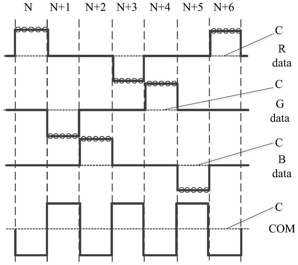
[0028] When the liquid crystal display panel in the transparent display mode includes red (R), green (G), and blue (B) three-color pixels, the timing diagram of the FSC display mode is as follows figure 1 As shown in the figure, the display time of each color picture includes three frames, and the data of three colors are written in sequence in the three frames. In the backlight lighting stage (R-LED, G-LED, B-LED), the data of the three colors and the ...


PUM


Abstract

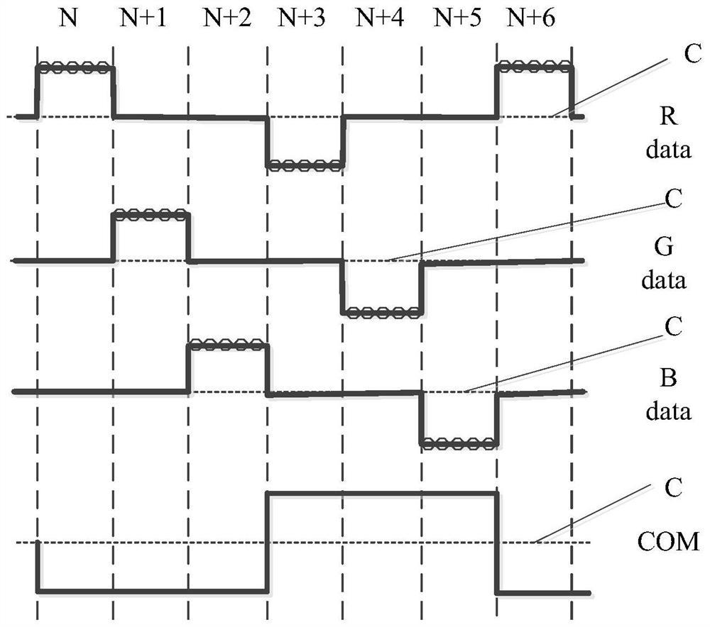
The invention provides a driving method, a driving circuit and a display device of a liquid crystal display panel, which belong to the technical field of display. Wherein, the driving method of the liquid crystal display panel includes: sending a common electrode signal to the common electrode line of the liquid crystal display panel, so that the common voltage signal passing through the common electrode line is in the unit of K frames between the first common voltage and the first common voltage. The two common voltages are reversed, the polarities of the first common voltage and the second common voltage are opposite with respect to the reference voltage, and K is an integer greater than 1. The technical scheme of the present invention can improve the color gamut of the display device, reduce the dynamic power consumption of the circuit system, and reduce the EMI.

Description

technical field [0001] The present invention relates to the field of display technology, in particular to a driving method, a driving circuit and a display device of a liquid crystal display panel. Background technique [0002] In the liquid crystal display panel of the related art, a higher driving voltage is required to drive the liquid crystal to invert. Since the data voltage transmitted on the data line cannot meet the requirements of the driving voltage, it is necessary to use a common voltage signal inversion method to increase the driving voltage. The inversion frequency of the voltage signal is the frame frequency. Due to the polarity inversion of adjacent frames, the voltage of the liquid crystal capacitor plate will change greatly, resulting in a longer charging and discharging time, compressing the lighting time, and resulting in a lower color gamut of the liquid crystal display panel. In addition, the inversion of the common voltage signal will lead to high dyna...

Claims


Application Information

Patent Timeline
Patent Type & Authority Patents(China)
IPC IPC(8): G09G3/36
CPCG09G3/3607G09G2320/0271
Inventor 刘宗民段立业王龙侯孟军黄继景吴琼马小惠
Owner BOE TECH GRP CO LTD
Learn More