Auxiliary positioning device for minimally invasive surgery of spine
A minimally invasive surgery and auxiliary positioning technology, applied in the field of medical devices, can solve problems such as puncture errors, lack of guide devices, and increase patient pain, and achieve the effects of strong practicability, convenient operation, and shaking prevention
- Summary
- Abstract
- Description
- Claims
- Application Information
AI Technical Summary
Problems solved by technology
Method used
Image
Examples
Embodiment 1
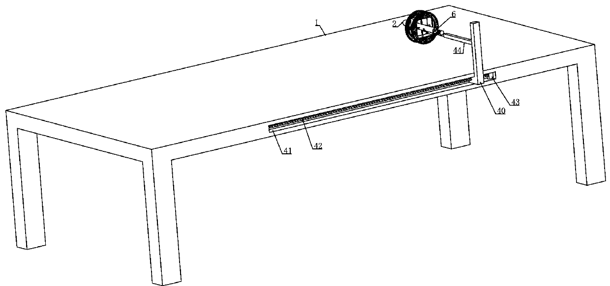
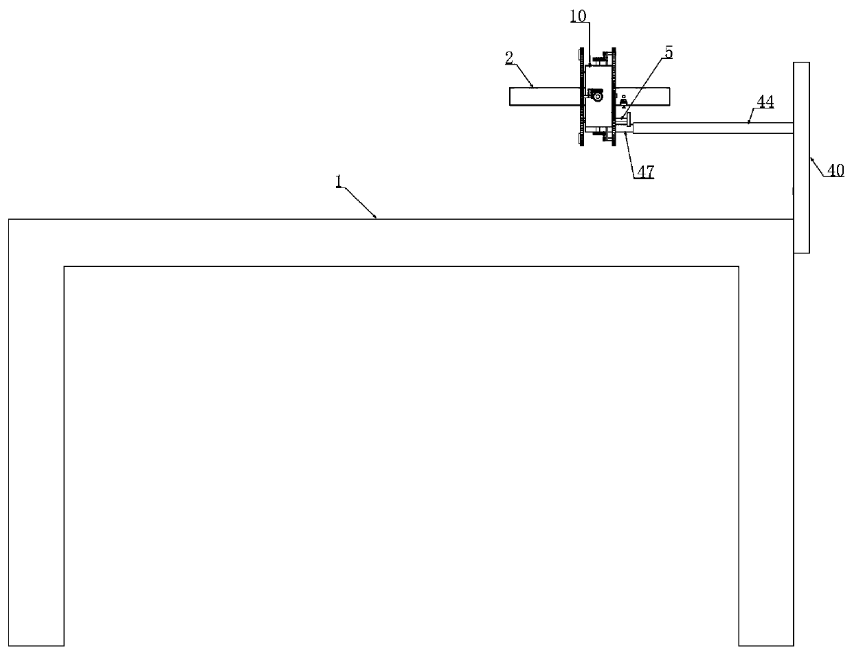
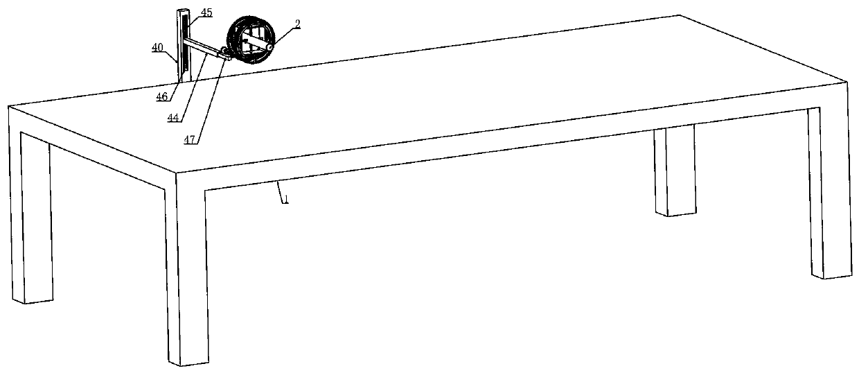
[0045] Embodiment 1, the auxiliary positioning device for minimally invasive spinal surgery, including a bed platform 1, is characterized in that the bed platform 1 is provided with a horizontal adjustment assembly, the horizontal adjustment assembly is provided with a vertical adjustment assembly, and the vertical adjustment assembly A longitudinal adjustment assembly is arranged on the top, and a support frame 10 is installed on the longitudinal adjustment assembly, and a first auxiliary cylinder 2 is arranged coaxially inside the support frame 10. The vertical ends and horizontal ends of the first auxiliary cylinder 2 are respectively The universal device is axially slidably connected to the sleeve 3 which is rotatably installed on the supporting frame 10. The sleeve 3 is placed outside the supporting frame 10 and connected with a one-way transmission device at one end. The supporting frame 10 is longitudinally The two sides are respectively rotated with ring drive devices, ...
Embodiment 2
[0052] Embodiment 2. On the basis of Embodiment 1, the annular drive device includes a first drive ring 7 and a second drive ring 8 that are coaxially spaced apart and fixedly connected. The inner surface of the first drive ring 7 and the second drive ring A plurality of first gear trains 9 are arranged at staggered intervals on the outer circumference of the two drive rings 8, and the side of the second drive ring 8 facing the support frame 10 is provided with an annular groove 11, and the support frame 10 faces the corresponding second gear. A number of connecting shafts 12 are fixedly arranged on the side wall of the driving ring 8, and several connecting shafts 12 are slidably connected in the annular groove 11, between the first driving ring 7 and the second driving ring 8 at the front end of the supporting frame 10. The first gear 13 that is rotatably mounted on the supporting frame 10 is meshed at both ends, and the upper and lower ends between the first driving ring 7 a...
Embodiment 3
[0057] Embodiment 3, on the basis of Embodiment 1, the one-way transmission device includes a worm wheel 15 sleeved on the end of the sleeve 3 placed outside the supporting frame 10, and the worm wheel 15 is engaged with a rotatably mounted on the supporting frame 10 The worm 16, the first gear 13 and the second gear 14 are respectively connected to the corresponding worm 16 through the pulley set 17.
[0058] When this embodiment is in use, refer to the attached Figure 9 As shown, the sleeve 3 is placed outside the support frame 10 and one end is covered with a built-in worm wheel 15, and the worm wheel 15 is engaged with a worm 16 that is rotatably mounted on the support frame 10. The first gear 13 and the second gear 14 are respectively passed through The pulley set 17 is connected to the corresponding worm 16, and the power is transmitted to the corresponding worm 16 through the pulley set 17 to realize the effect of driving the worm wheel 15 to rotate, and the worm wheel...
PUM
 Abstract
Description
Claims
Application Information
 - R&D
- Intellectual Property
- Life Sciences
- Materials
- Tech Scout
- Unparalleled Data Quality
- Higher Quality Content
- 60% Fewer Hallucinations
Browse by: Latest US Patents, China's latest patents, Technical Efficacy Thesaurus, Application Domain, Technology Topic, Popular Technical Reports.
© 2025 PatSnap. All rights reserved.Legal|Privacy policy|Modern Slavery Act Transparency Statement|Sitemap|About US| Contact US: help@patsnap.com


