Electronically controlled skimmer

A skimmer and electric controller technology, applied in chemical instruments and methods, filtration separation, separation methods, etc., can solve the problems of low slag removal efficiency, low cleaning efficiency, and high labor intensity, and achieve safe and convenient operation and low operating costs. The effect of low and high slag collection rate

Pending Publication Date: 2019-10-22
珠海横琴新区圣大环保科技有限公司
View PDF0 Cites 0 Cited by
  • Summary
  • Abstract
  • Description
  • Claims
  • Application Information

AI Technical Summary

Problems solved by technology

This cleaning method has low cleaning efficiency, high labor intensity, high labor cost, and poor safety.
[0004] 2. In small ornamental ponds, a small floating skimmer is also used to clean up floating objects on the water surface, such as a pond skimmer imported from Germany. It is made of PC plastic and consists of a collection basket, a filter layer, a floating bucket and a water pump installed at the bottom of the bucket. Composition, when the water pump pumps water, the water in the bucket forms a vortex, which sucks the debris on the water surface into the collection basket from the pool surface, and plays the role of cleaning up floating objects such as leaves and paper scraps; its technical problem is that its technical structure determines that it is only suitable for For small water surfaces, such as small landscape fish ponds, mirror pools, etc., the water surface treatment capacity is small; because the device floats on the water surface, its support and balance are not easy to control, and its ability to resist water surface fluctuations is poor; the water inlet of the collection basket is narrow and has a large volume Small, can only collect small floating objects like leaves, and the frequency of manual cleaning of debris is high
[0005] To sum up, the existing main technical problems are: low slag removal efficiency, high cost, poor safety, low degree of automation, and it is not suitable for cleaning floating objects in lakes with large water surface

Method used


Image

  • Electronically controlled skimmer
  • Electronically controlled skimmer
  • Electronically controlled skimmer

Examples


Embodiment Construction

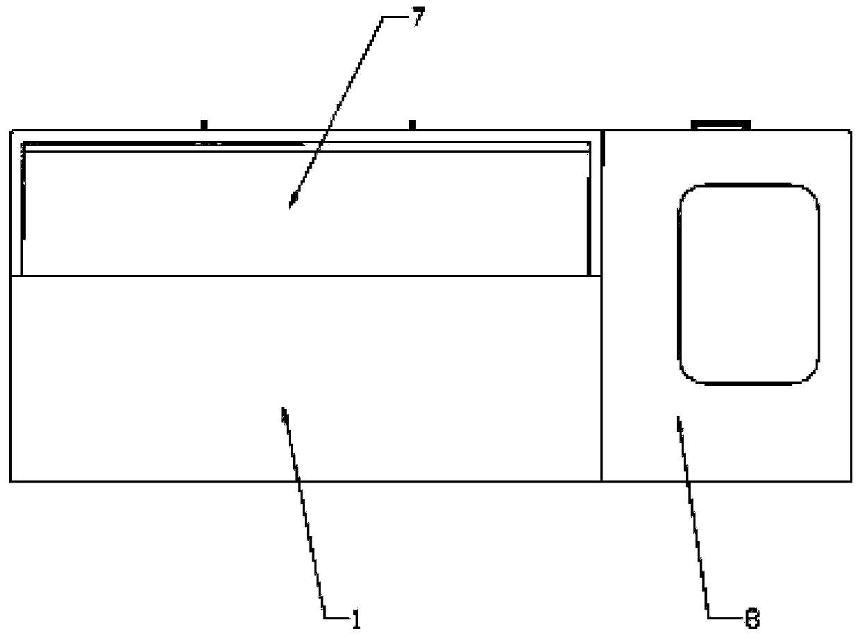
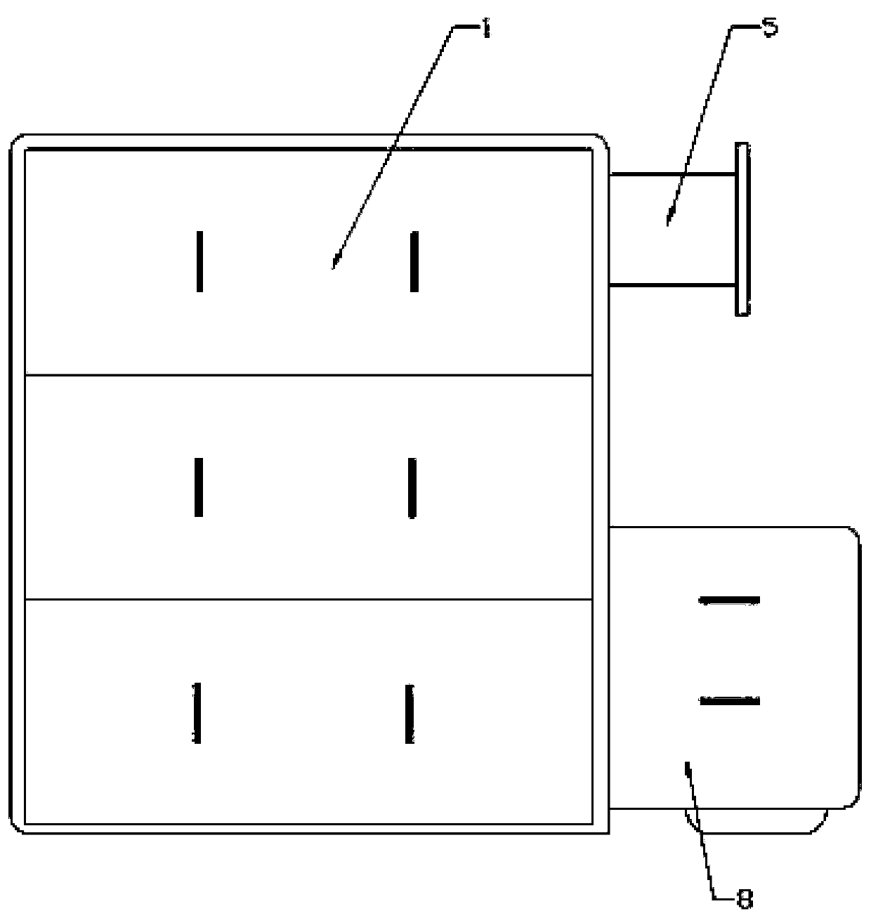
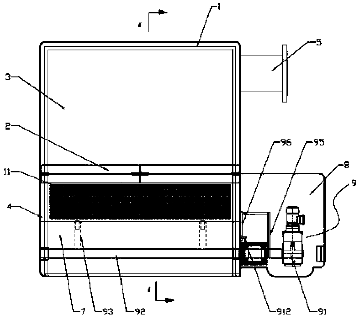
[0023] Such as Figure 1 to Figure 5 As shown, in this embodiment, the present invention includes a main box body 1, and a filter plate 2 is arranged inside the main box body 1, and two sides of the inside of the main box body 1 are welded to match the filter plate 2. The guide groove, the filter plate 2 is adapted to be inserted in the guide groove, this installation method makes the filter plate 2 separate the main box body 1 into a clean water storage tank 3 and a sedimentation tank 4, and the sedimentation tank 4 A scum collection basket 11 is installed, and the scum collection basket 11 is welded by a permeable orifice plate, the clear water storage tank 3 is provided with a drain pipe 5, the sedimentation tank 4 is provided with a water inlet 6, and the water inlet An adjustable slag-introducing water retaining plate 7 is obliquely installed at the nozzle 6, and a waterproof case 8 is provided at one end of the main box body 1, and a water-proof case 8 connected with the...


PUM


Abstract

The invention discloses an electronically controlled skimmer, and aims at providing the electronically controlled skimmer with high working efficiency, safe and convenient operation and low operationcost. The skimmer includes a main tank. A filter plate is arranged in the main tank. The filter plate divides the inside of the main box into a clear water storage tank and a deposition tank. A waterdrain pipe is arranged on the clear water storage tank. A scum collection basket and a water inlet are arranged in the deposition tank. The water inlet is obliquely provided with an adjustable slag guiding water baffle plate. A waterproof cabinet is arranged on one end of the main tank. A steering control system connected to the adjustable slag guiding water baffle plate is arranged in the waterproof cabinet. The electronically controlled skimmer is applied to the technical field of skimmers.

Description

technical field [0001] The invention relates to a skimmer, in particular to an electronically controlled skimmer. Background technique [0002] Static lakes, such as landscape lakes and artificial lakes, often have leaves, grasses, branches, paper scraps, plastic bags and other debris floating on the water surface when it is windy and rainy, polluting the water body, affecting the landscape effect, and deteriorating the surrounding environment. Therefore, there is a need for a facility to continuously remove debris on the water surface, not only to keep the water surface clean, but also to coordinate with the water surface landscape or enhance the landscape effect. The following is the implementation plan of the existing removal technology: [0003] 1. Most park lakes generally use artificially driven boats to clean up floating debris such as leaves and algae on the water surface, or directly use long-pole nets to salvage floating debris in small artificial lake waters. Thi...

Claims


Application Information

Patent Timeline
IPC IPC(8): B01D36/04
CPCB01D36/04
Inventor 金淑兰孙震
Owner 珠海横琴新区圣大环保科技有限公司
Why Eureka
Try Eureka