Machining method of second last stage and last stage moving blades of steam turbine

A processing method, a second-end technology, applied in the processing field of steam turbine blades, can solve the problems of insufficient efficiency and dimensional accuracy, great influence on product quality, and poor consistency, so as to shorten the product processing cycle, The effect of reducing labor costs and avoiding errors

Active Publication Date: 2019-10-22
四川飞哥科技有限公司
View PDF7 Cites 10 Cited by
  • Summary
  • Abstract
  • Description
  • Claims
  • Application Information

AI Technical Summary

Problems solved by technology

It is pointed out in the patent that the structure of the five-prong blade root is complex, and its blade root plays an important role in the steam turbine unit. Therefore, the precision of the blade itself, especially the blade root profile, is highly demanding. The existing process plan is : Datum plane processing is basically processed by ordinary flat milling and horizontal milling machine tools, and each process is processed in sequence, that is, each datum positioning plane is processed in sequence, and each datum plane needs a process to complete. The disadvantage of sequential processing is that it is easy to produce Accumulated errors, accumulated errors in multiple clamping and accumulated errors in processing, the consistency of ordinary machine tools is not very good, and the efficiency and dimensional accuracy are far from meeting the requirements, which inevitably has a greater impact on product quality. And the consistency of the product is poor, while the production efficiency is low, the processing cycle is long, the number of machine tools required is large, and the production cost is high. With the gradual increase of human resource costs and the emergence of CNC machine tools

Method used


Image

  • Machining method of second last stage and last stage moving blades of steam turbine
  • Machining method of second last stage and last stage moving blades of steam turbine

Examples


Embodiment

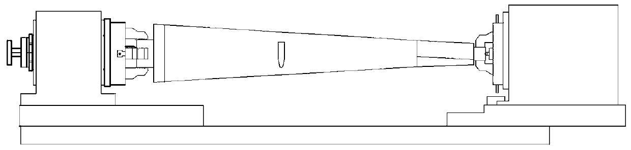
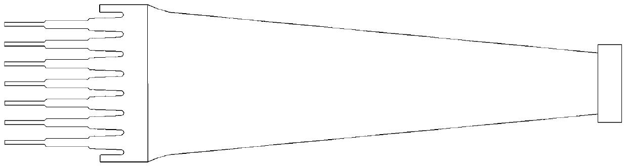
[0027] Example: as attached figure 1 and 2 As shown in the figure, a processing method for the second last stage and the last stage moving blade of a steam turbine includes finding three center positioning holes on the blade blank, positioning the blade blank through the three pinholes, and matching the blade blank on the The three center positioning holes of the blade are installed on the four-axis numerical control vertical machining center, and the invention is processed according to the fork-type blade root blade with the inner back concave-convex surface of the blade blade root.

[0028] S1: the milling two-dimensional code identification surface, two-dimensional code marking and leaf crown process head;

[0029] S2: the inner radial reference plane of the rough and fine milled blade blank; sawing and milling blade root end face; the air inlet and outlet sides of the rough and fine milling blade blank; the two positioning shoulders of the rough and fine milling blade bla...


PUM

PropertyMeasurementUnit
lengthaaaaaaaaaa

Abstract

The invention discloses a machining method of the second last stage and the last stage moving blades of a steam turbine. The machining method comprises the following steps of finding three center positioning holes of blade blanks; and arranging the blade blanks on a four-axis numerical control vertical processing center by the method of positioning three top pinholes in combination with the threecenter positioning holes on the blade blanks. According to the characteristics of the machining method of the fork blade root blades, in particular to the step 2 in the claim that the reference of theblades is converted from the three center holes of the blank reference to the final reference plane of the blades and the machining is completed with each part of a blade steam passage at one time, the risk that the blade blanks cannot be machined due to the conversion reference error is reduced in the subsequent procedures; and the positioning reference planes used in different processing procedures are reasonably selected, and one-time clamping is adopted to complete multiple processing procedures of blades in the prior art, so that the number of calibration is reduced so as to effectivelyavoid the accumulated error, the machining accuracy is improved, the product machining cycle is shortened, the number of machine tools needed is reduced, and the production cost is reduced.

Description

technical field [0001] The invention relates to the technical field of processing steam turbine blades. [0002] Specifically, it relates to a processing method of a five-pronged, seven-pronged, and eight-pronged blade root with a crown moving blade. Background technique [0003] With the advancement of science and technology, the development of steam turbines has made great progress, especially in the production and research of large steam turbines, there have been major technological breakthroughs. The surface processing technology of steam turbine blades has a significant impact on the service life of steam turbines and the conversion efficiency of kinetic energy. It plays a decisive role, especially for the last stage of the steam turbine blade and the fork-shaped root blade of the last stage. The length of the steam passage can reach 500mm to more than 1100mm. It will be deformed. Because the structure of the seven-pronged or eight-pronged steam turbine blade is more c...

Claims


Application Information

Patent Timeline
Patent Type & Authority Applications(China)
IPC IPC(8): B23P15/02
CPCB23P15/02
Inventor 文建飞
Owner 四川飞哥科技有限公司
Why Eureka
Try Eureka