A method for solving the grinding wheel track in the end edge clearance grinding process of ball end mills

A technology of ball end mill and gap grinding, which is applied in the direction of milling cutter, milling machine equipment, metal processing equipment, etc., can solve the problems of unsafe ball end milling and large grinding allowance, and achieve the purpose of making up for the end edge technology. Insufficient, reducing grinding allowance, improving the effect of rotary shape

Active Publication Date: 2021-02-19
SOUTHWEST JIAOTONG UNIV +1
View PDF9 Cites 0 Cited by
  • Summary
  • Abstract
  • Description
  • Claims
  • Application Information

AI Technical Summary

Problems solved by technology

For cylindrical bars, the grinding allowance is large when grinding the flank, especially for hard alloys such as hard alloys, it is not safe to directly use the flank process to form the ball head

Method used


Image

  • A method for solving the grinding wheel track in the end edge clearance grinding process of ball end mills
  • A method for solving the grinding wheel track in the end edge clearance grinding process of ball end mills
  • A method for solving the grinding wheel track in the end edge clearance grinding process of ball end mills

Examples


Embodiment Construction

[0056] The present invention will be described in further detail below in conjunction with the accompanying drawings and specific embodiments.

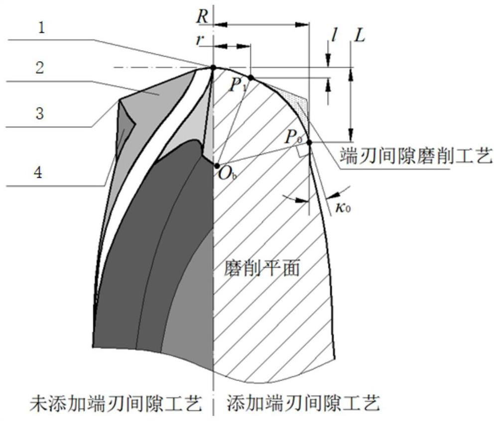
[0057]Step 1: Define the geometric parameters of the end edge clearance.

[0058] like figure 1 As shown in Fig. 1, the grinding plane is first selected as a certain plane passing through the axis of the rotating body of the tool, and the angle between it and the cutting edge is specified by the user to achieve the best grinding effect. In order to make the contour between two adjacent edges of the ball-end cutter close to the spherical contour, the present invention defines the outer contour of the end edge gap as a section of arc on the grinding plane. Let the starting point of the arc be P 0 , the end point is P 1 , the arc center is O b .

[0059] (1) Starting position. Arc starting point P 0 The location of is constrained by the starting radius R and the starting length L. where the starting point radius R is defined as p...


PUM


Abstract

The present invention proposes a method for solving the grinding wheel trajectory of the end edge clearance grinding process of a ball end mill. Firstly, the geometric parameters of the end edge clearance and the grinding wheel grinding posture are defined, and then the initial grinding trajectory and the end edge under the grinding coordinate system are calculated. The grinding trajectory after adding various process parameters during the grinding process of gap technology, then calculate the axis vector of the grinding wheel, and finally transform the grinding trajectory to the workpiece coordinate system. The grinding trajectory of the present invention can remove the sharp point of the end edge, improve the rotary shape of the end of the ball end mill, thereby making up for the deficiency of the end edge technology of the ball end mill; and can be used as a rough machining process to reduce the grinding residue of the flank amount, to achieve the purpose of protecting the workpiece and the grinding wheel.

Description

technical field [0001] The invention relates to the technical field of integral end milling cutter processing, in particular to a method for solving a grinding wheel trajectory of a ball end milling cutter end edge clearance grinding process. Background technique [0002] When processing ball-end milling cutters with a small number of edges such as two-blade and three-blade, it is often found that the connection between the flank of the ball head and the spiral groove of the peripheral edge protrudes outwards, forming a sharp point of the end edge. Once the distance from the highest point of the tip of the end blade to the rotary axis is greater than the radius of the ball head, the shape of the body of revolution formed by the ball head part during high-speed rotation will no longer be a regular spherical shape, which will seriously affect the quality of the machined surface. Therefore, in the manufacturing process of the ball end mill, it is necessary to add a process to r...

Claims


Application Information

Patent Timeline
Patent Type & Authority Patents(China)
IPC IPC(8): B24B1/00B24B3/02
CPCB24B1/00B24B3/02
Inventor 丁国富罗斌江磊丁国华陈思远马术文梁红琴
Owner SOUTHWEST JIAOTONG UNIV
Why Eureka
Try Eureka