Surface deburring device for manufacturing bearing steel balls

A bearing steel ball and deburring technology, which is applied to manufacturing tools, metal processing equipment, grinding/polishing equipment, etc., can solve the problems of low deburring efficiency and single function of the grinding machine

Active Publication Date: 2019-10-22
宁波奉化精瑞钢球有限公司
View PDF11 Cites 10 Cited by
  • Summary
  • Abstract
  • Description
  • Claims
  • Application Information

AI Technical Summary

Problems solved by technology

[0002] When producing bearing steel balls in large quantities, in order to make the surface of bearing steel balls smoother, it is necessary to deburr the surface of bearing steel balls. Usually, when deburring large quantities of bearing steel balls, a large number of steel balls are put into the grinding machine, and then Put in the grinding liquid, and then the grinding machine rotates to drive the steel ball and the grinding liquid to deburr. However, the existing grinding machine has a single function and can only rotate in one direction, so the deburring efficiency is low. Therefore, we propose a bearing Surface deburring equipment for steel ball manufacturing in order to solve the problems raised above

Method used


Image

  • Surface deburring device for manufacturing bearing steel balls
  • Surface deburring device for manufacturing bearing steel balls
  • Surface deburring device for manufacturing bearing steel balls

Examples


Embodiment Construction

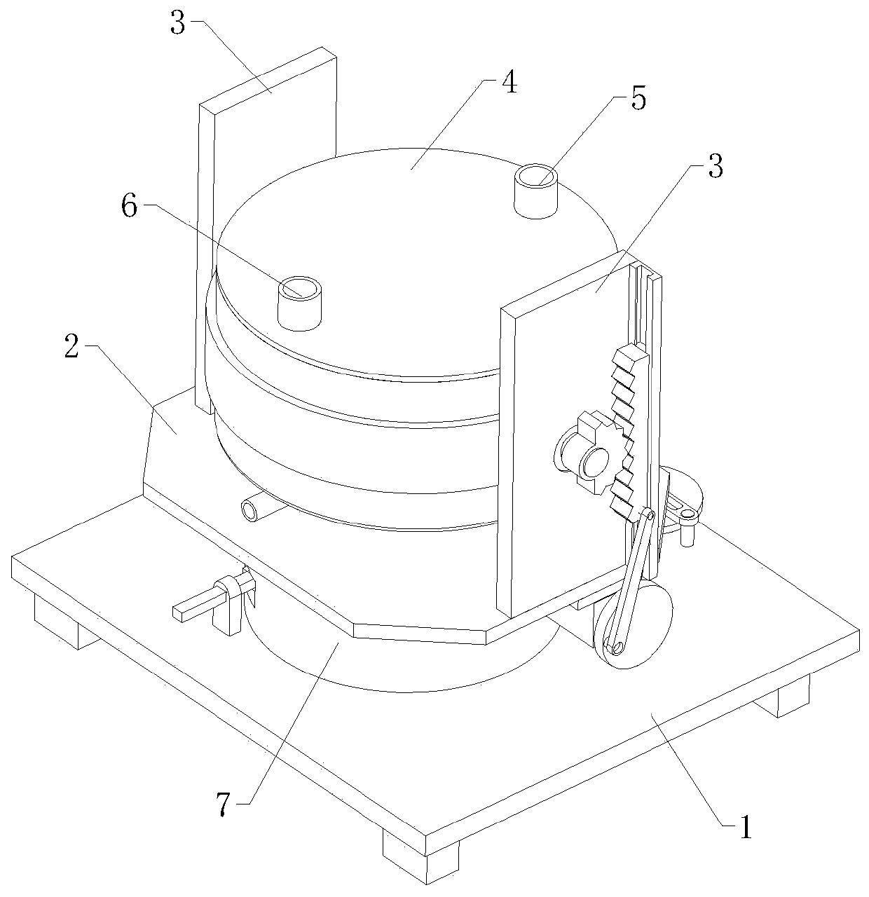
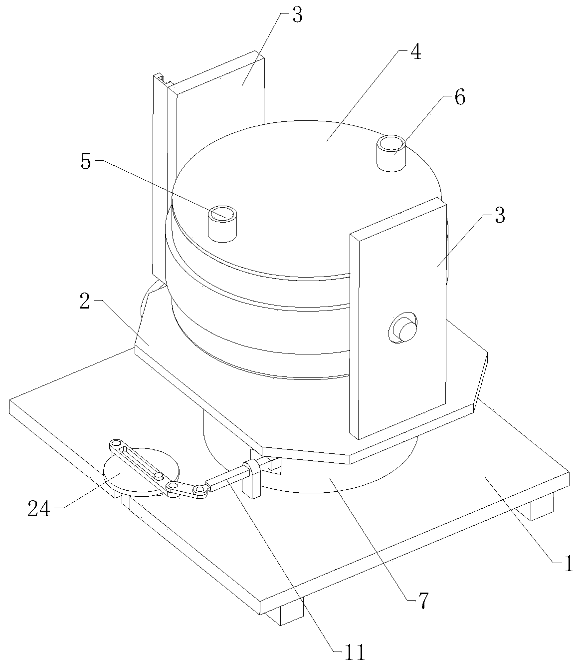
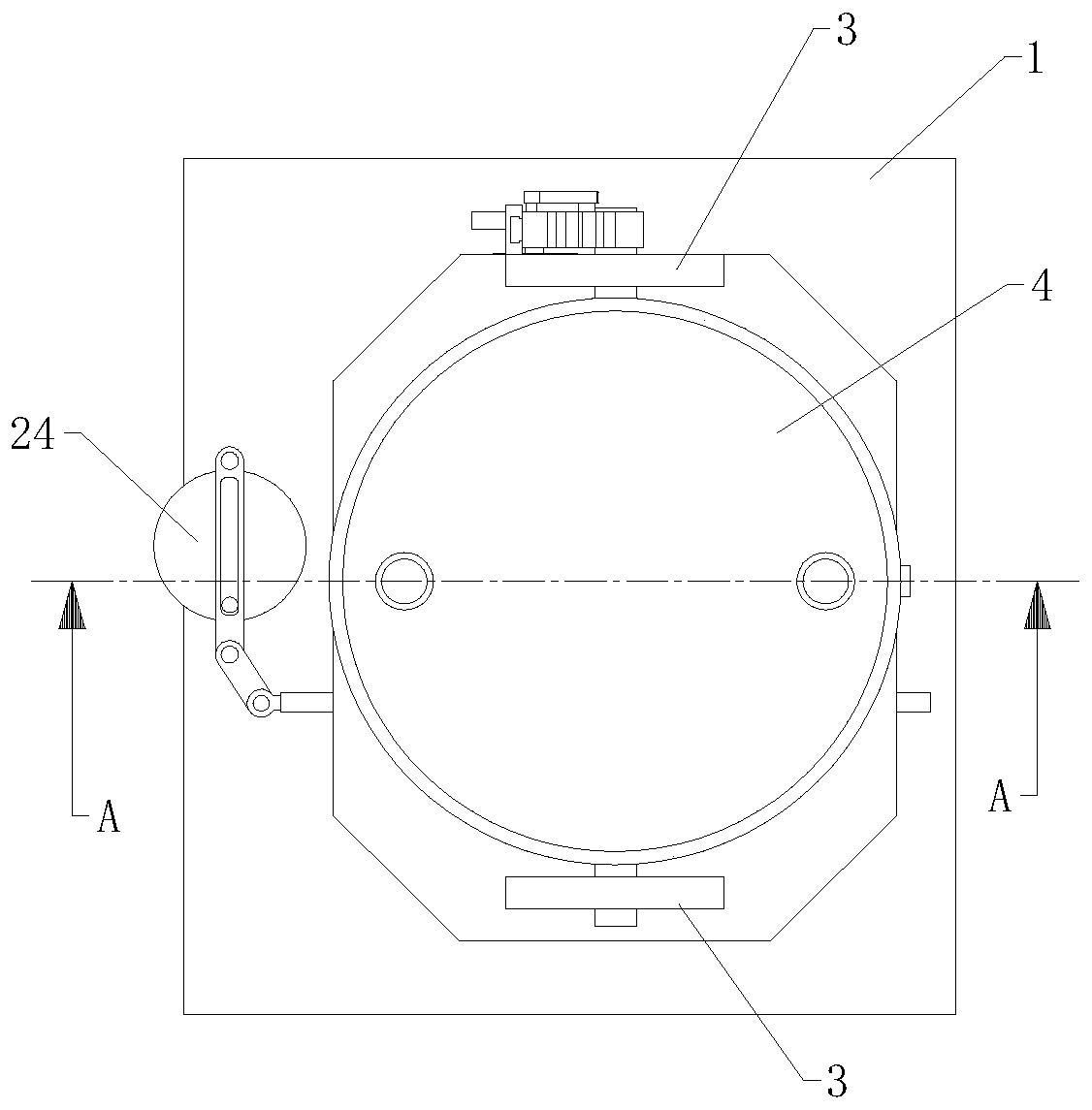
[0025] The technical solutions of the present invention will be further described below in conjunction with the accompanying drawings and through specific implementation methods.

[0026] Wherein, the accompanying drawings are only for illustrative purposes, showing only schematic diagrams, rather than physical drawings, and should not be construed as limitations on this patent; in order to better illustrate the embodiments of the present invention, some parts of the accompanying drawings will be omitted, Enlargement or reduction does not represent the size of the actual product; for those skilled in the art, it is understandable that certain known structures and their descriptions in the drawings may be omitted.

[0027]In the drawings of the embodiments of the present invention, the same or similar symbols correspond to the same or similar components; , "inner", "outer" and other indicated orientations or positional relationships are based on the orientations or positional r...


PUM


Abstract

The invention relates to the field of bearing steel ball processing, in particular to a surface deburring device for manufacturing bearing steel balls. The surface deburring device comprises a base and further comprises a grinding mechanism, a rocking mechanism and a horizontal swinging mechanism; the horizontal swinging mechanism comprises a rotating plate capable of doing positive and negative reciprocated motion in the horizontal state, and the rotating plate is horizontally arranged above the base; the rocking mechanism includes two connecting vertical plates, and the two connecting vertical plates are symmetric and are arranged at the top of the rotating plate in a spaced manner; and the grinding mechanism includes a grinding pot, the two ends of the grinding pot are movably arrangedbetween the two connecting vertical plates through a rotating shaft, the inside of the grinding pot is provided with a discharging assembly, and the top of the grinding tank is provided with a liquidinlet pipe and a feeding pipe. The surface deburring device can comprehensively conduct deburring on the steel balls in a large batch, and therefore the deburring efficiency is improved.

Description

technical field [0001] The invention relates to the field of bearing steel ball processing, in particular to a surface deburring device for bearing steel ball manufacturing. Background technique [0002] When producing bearing steel balls in large quantities, in order to make the surface of bearing steel balls smoother, it is necessary to deburr the surface of bearing steel balls. Usually, when deburring large quantities of bearing steel balls, a large number of steel balls are put into the grinding machine, and then Put in the grinding liquid, and then the grinding machine rotates to drive the steel ball and the grinding liquid to deburr. However, the existing grinding machine has a single function and can only rotate in one direction, so the deburring efficiency is low. Therefore, we propose a bearing Surface deburring equipment for steel ball manufacturing, in order to solve the problems raised above. Contents of the invention [0003] The object of the present inventi...

Claims


Application Information

Patent Timeline
Patent Type & Authority Applications(China)
IPC IPC(8): B24B31/12B24B41/02B24B41/00B24B31/06B24B47/12B24B57/02
CPCB24B31/06B24B31/12B24B41/005B24B41/02B24B47/12B24B57/02
Inventor 李建军李宁
Owner 宁波奉化精瑞钢球有限公司
Why Eureka
Try Eureka