Automatic feeding device of spring grinding machine

An automatic feeding and spring grinding machine technology, which is applied in the field of spring processing, can solve the problems of reduced efficiency, damage to fixtures and soft pipes, and low placement efficiency, so as to avoid excessive deformation damage, prolong the service life of equipment, and reduce processing costs. Effect

Active Publication Date: 2019-10-22
TIANJIN SAIXIANG M&E ENG CO LTD
View PDF7 Cites 8 Cited by
  • Summary
  • Abstract
  • Description
  • Claims
  • Application Information

AI Technical Summary

Problems solved by technology

[0004] Before the grinding device grinds the springs, the springs to be processed need to be placed in the fixtures. The traditional loading method is to manually place the springs in the fixtures. This loading method is inefficient and cannot be placed in time. The fixtures are all equipped with springs, which will reduce the efficiency. If you are tired and distracted during the placement process, it is easy to cause safety accidents
[0005] In order to solve the above problems, a vibrating plate is used instead of manual feeding. The discharge position of the vibrating plate is connected to one of the clamps through the transmission pipeline of the conveying spring, so as to realize the function of automatic feeding. However, this feeding method Although the problem of low placement efficiency is sol

Method used


Image

  • Automatic feeding device of spring grinding machine
  • Automatic feeding device of spring grinding machine
  • Automatic feeding device of spring grinding machine

Examples


Embodiment Construction

[0026] The technical solutions of the present invention will be clearly and completely described below in conjunction with the accompanying drawings. Apparently, the described embodiments are some of the embodiments of the present invention, but not all of them. Based on the embodiments of the present invention, all other embodiments obtained by persons of ordinary skill in the art without making creative efforts belong to the protection scope of the present invention.

[0027] In the description of the present invention, it should be noted that the terms "center", "upper", "lower", "left", "right", "vertical", "horizontal", "inner", "outer" etc. The indicated orientation or positional relationship is based on the orientation or positional relationship shown in the drawings, and is only for the convenience of describing the present invention and simplifying the description, rather than indicating or implying that the referred device or element must have a specific orientation, ...


PUM


Abstract

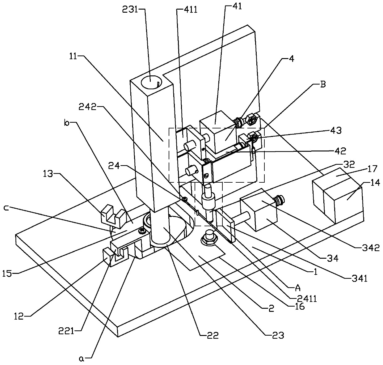
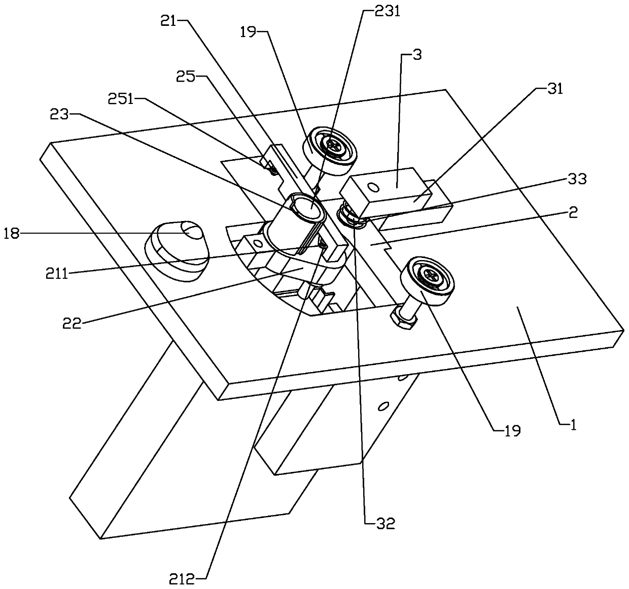
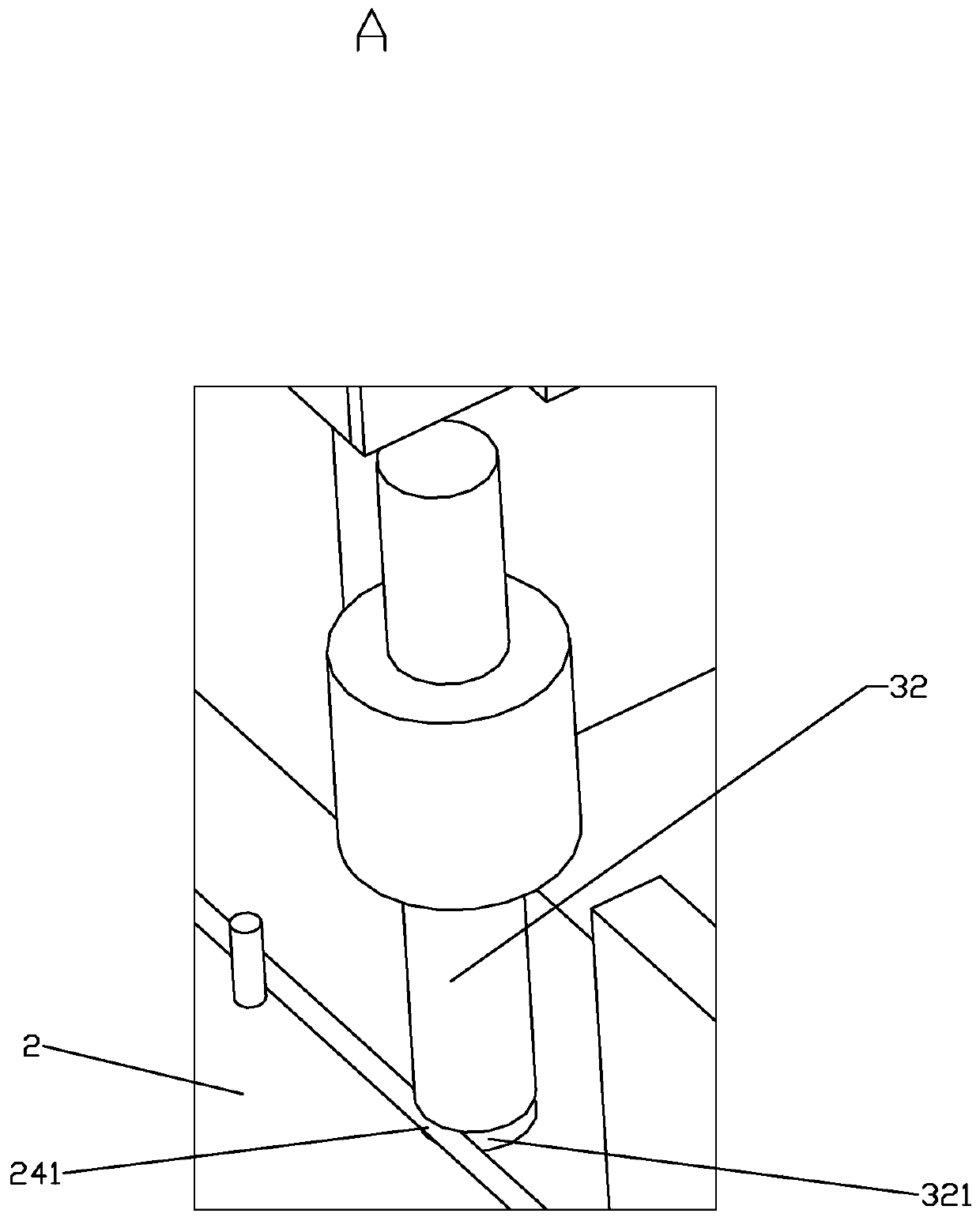
The invention relates to an automatic feeding device of a spring grinding machine. The automatic feeding device comprises a feeding platform, a linkage arm, a side swing arm, a movable feeding pipeline, a fixed feeding pipeline, a lifting seat, a first induction mechanism, a second induction mechanism, a lifting device and a first alarm mechanism, wherein the lifting device is arranged between thelifting seat and the feeding platform, and used for lifting the lifting seat upwards; a swing cavity penetrating through vertically is formed in the feeding platform; the linkage arm is used for linking the side swing arm with the lifting seat; the side swing arm horizontally swings in the swing cavity; a fixed feeding pipeline is arranged on the side swing arm; the two ends of the horizontal swing track of the side swing arm are respectively a first position and a second position; and when a spring to be processed is clamped between the tail end of the movable feeding pipeline and a clamp, the side swing arm is driven to swing to the second position, and the lifting seat is lifted by the lifting device to separate the spring to be processed from the clamp. By adopting the scheme, the automatic feeding device is high in feeding efficiency and capable of avoiding spring deformation and equipment damage.

Description

technical field [0001] The invention relates to the field of spring processing, in particular to an automatic feeding device for a spring grinding machine. Background technique [0002] A spring is a mechanical part that uses elasticity to work. Parts made of elastic materials are deformed under the action of external force, and return to their original shape after the external force is removed. Generally made of spring steel. The types of springs are complex and diverse, divided by shape, mainly cylindrical springs, scroll springs, leaf springs, special-shaped springs, etc. [0003] The spring grinding machine is a kind of equipment used to process the length of cylindrical springs. It usually includes a base, a turntable, a motor and a grinding device. The edge of the turntable is equidistantly provided with a plurality of fixtures for placing the springs to be processed, one of which is The position of the fixture corresponds to the grinding device, and the turntable r...

Claims


Application Information

Patent Timeline
IPC IPC(8): B24B41/06B24B41/00B24B55/00B24B49/00
CPCB24B41/005B24B41/06B24B49/00B24B55/00
Inventor 黄其祥
Owner TIANJIN SAIXIANG M&E ENG CO LTD
Why Eureka
Try Eureka