A pressure relief valve for power electrical transformers

A technology of electric power and transformers, applied in the direction of valve operation/release devices, balance valves, valve devices, etc.

Active Publication Date: 2021-03-16
九江检安石化工程有限公司
View PDF6 Cites 0 Cited by
  • Summary
  • Abstract
  • Description
  • Claims
  • Application Information

AI Technical Summary

Problems solved by technology

[0005] The invention provides a pressure relief valve for electric power transformers, which has the advantage of being convenient for buffering the instantaneous pressure in the transformer, and solves the technical problems mentioned in the background technology

Method used


Image

  • A pressure relief valve for power electrical transformers
  • A pressure relief valve for power electrical transformers

Examples


Embodiment Construction

[0015] The following will clearly and completely describe the technical solutions in the embodiments of the present invention with reference to the accompanying drawings in the embodiments of the present invention. Obviously, the described embodiments are only some, not all, embodiments of the present invention. Based on the embodiments of the present invention, all other embodiments obtained by persons of ordinary skill in the art without making creative efforts belong to the protection scope of the present invention.

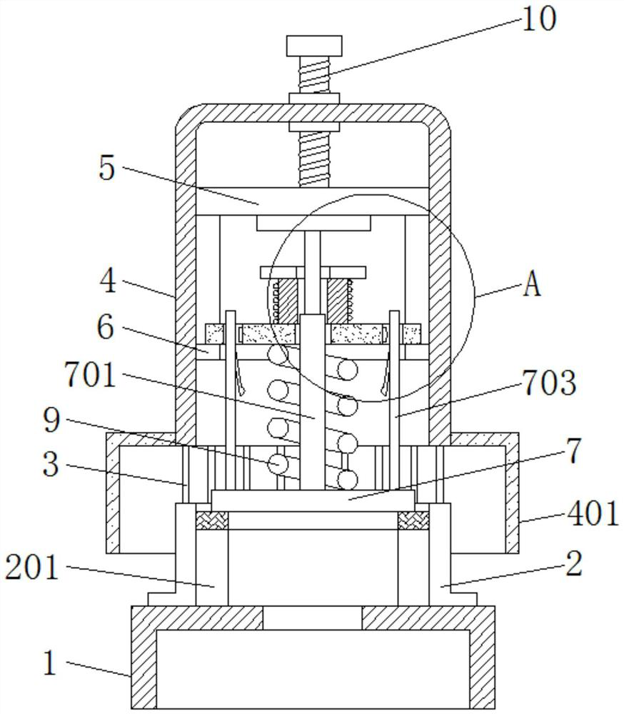
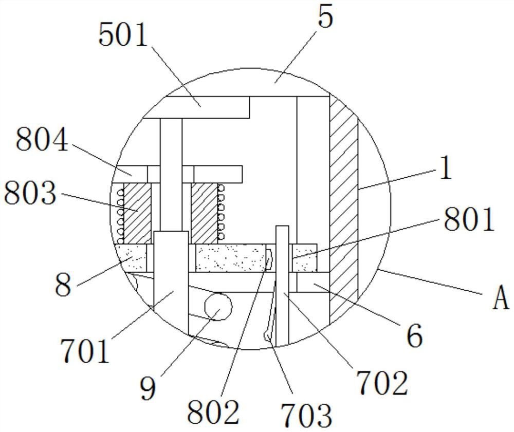
[0016] see Figure 1-2 , a pressure release valve for power and electrical transformers, including a valve tube channel 1, the bottom of the valve tube channel 1 is fixedly sleeved on the transformer, connected to the cooling oil inside the transformer, and the top of the valve tube channel 1 is fixedly connected with a sleeve 2, A valve seat 201 is fixed inside the sleeve 2, and the top of the sleeve 2 is fixedly connected with the connecting shaft 3 arranged...


PUM


Abstract

The invention relates to the field of power equipment, and discloses a pressure release valve for an electric power transformer. The pressure release valve comprises a valve pipe channel, a sleeve, avalve seat, a valve cylinder and a valve rod, wherein a driven plate is arranged at the top of an inner cavity of the valve cylinder; a positioning plate is arranged in the middle of the inner cavityof the valve cylinder; a spring is arranged between the positioning plate and the valve cylinder; and a first magnet and a second magnet with the same magnetic poles are respectively arranged betweenthe driven plate and the positioning plate. According to the pressure release valve, through the design of the first magnet, the second magnet and an electromagnet, when a valve core is moved upwardsby the instantaneous impact force in the transformer, an electric elastic sheet makes contact with an electric gasket before the spring bears the maximum limit , so that the electromagnet is electrified to generate suction force with the first magnet, the partial repulsive force of the first magnet to the second magnet is overcome, and the spring dose not bear the maximum pressure and is effectively buffered; and therefore, the spring can be effectively guaranteed to return to the initial state smoothly, and the release valve can be tightly closed.

Description

technical field [0001] The invention relates to the field of electric equipment, in particular to a pressure relief valve for electric power transformers. Background technique [0002] A power transformer is a device that converts an AC voltage (current) of a certain value into another voltage (current) with the same frequency or several different values. A common oil-immersed transformer consists of a thermometer, a moisture absorber, an oil standard, a storage Oil tank, pressure relief valve or explosion-proof tube, gas relay, high-voltage bushing, low-pressure bushing and other structures, among which, the pressure relief valve or explosion-proof tube is a device that releases the internal pressure of the transformer to prevent accidents from expanding. Because the explosion-proof tube is more advanced, its quality determines the anti-danger coefficient of the transformer. [0003] The working principle of the existing pressure relief valve is as follows: when the pressu...

Claims


Application Information

Patent Timeline
Patent Type & Authority Patents(China)
IPC IPC(8): F16K17/04F16K17/164F16K31/06F16K31/08F16K47/00
CPCF16K17/0433F16K17/048F16K17/164F16K31/0675F16K31/0696F16K31/082F16K47/00
Inventor 吴文地
Owner 九江检安石化工程有限公司
Why Eureka
Try Eureka