
Radial sliding bearing wear on-line measuring device based on inductance measurement

A technology of radial sliding and bearing wear, applied in the field of detection, can solve the problem of not being able to obtain the wear amount of radial sliding bearings, and achieve the effect of eliminating external interference, improving measurement accuracy and high sensitivity

Inactive Publication Date: 2019-10-22
东北大学秦皇岛分校
View PDF14 Cites 0 Cited by
  • Summary
  • Abstract
  • Description
  • Claims
  • Application Information

AI Technical Summary

Problems solved by technology

[0002] The monitoring methods for the wear state of radial sliding bearings mainly include oil method, temperature method, vibration method and strain method, etc., limited by the use environment of radial sliding bearings, these methods cannot accurately monitor the wear of radial sliding bearings in real time Quantitative detection
Wuhan University of Technology proposed a "Verification Test Bench and Method for Diesel Engine Sliding Bearing Wear Thermoelectric Monitoring System" based on the temperature method (Patent No.: CN 108844739 A). This method can only locate the fault point, but cannot obtain the path Amount of wear to sliding bearings

Method used


Image

  • Radial sliding bearing wear on-line measuring device based on inductance measurement
  • Radial sliding bearing wear on-line measuring device based on inductance measurement

Examples


Embodiment Construction

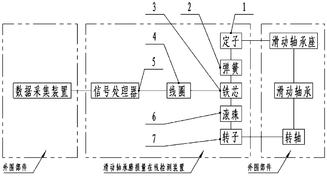
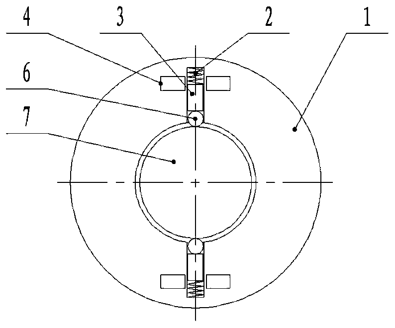
[0016] like figure 1 , 2 As shown, an on-line detection device for radial sliding bearing wear based on inductance measurement includes a stator 1, a rotor 7, a coil 4, an iron core 3, a spring 2, a ball 6 and a signal processor 5, and the stator 1 and The sliding bearing seat is coaxially fixedly connected, the rotor 7 is coaxially fixedly connected with the rotating shaft, the stator 1 is provided with radial blind holes, and the radial blind holes are two and arranged symmetrically on the circumference; the spring 2, The number of iron core 3, coil 4 and ball 6 is two; the coil 4 is coaxially fixed outside the radial blind hole; the spring 2 is placed in the radial blind hole, and the iron core 3 is placed in the radial blind hole to be close to the spring 2 and coaxial with the coil 4, and the ball 6 is placed in the radial blind hole between the iron core 3 and the rotor 7 Between, the spring 2 ensures that the ball 6 is in close contact with the rotor 7; the coil 4 is ...


PUM


Abstract

The invention relates to a radial sliding bearing wear on-line measuring device based on inductance measurement. The technical scheme is characterized in that the device comprises a stator, a rotor, acoil, an iron core, a spring, a roll ball and a signal processor. The stator is coaxially and fixedly connected with a sliding bearing pedestal; the rotor is coaxially and fixedly connected with a rotating shaft; the stator is provided with a radial blind hole; the coil is coaxially fixed outside of the radial blind hole; the spring is arranged in the radial blind hole; the iron core is arrangedin the radial blind hole and is tightly attached to the spring and coaxial with the coil; and the roll ball is arranged in the radial blind hole and between the iron core and the rotor. The coil is used for collecting position change of the iron core, forming a monitoring signal and sending the monitoring signal to the signal processor; and the signal processor is used for analyzing the monitoringsignal and converting the signal into position change amount of the rotating shaft and outputting the position change amount to a data acquisition device. The device can realize on-line measurement of wear of a radial sliding bearing.

Description

technical field [0001] The invention belongs to the technical field of detection, and in particular relates to an on-line detection device for radial sliding bearing wear based on inductance measurement. Background technique [0002] The monitoring methods for the wear state of radial sliding bearings mainly include oil method, temperature method, vibration method and strain method, etc., limited by the use environment of radial sliding bearings, these methods cannot accurately monitor the wear of radial sliding bearings in real time Quantitative detection. Wuhan University of Technology proposed a "Verification Test Bench and Method for Diesel Engine Sliding Bearing Wear Thermoelectric Monitoring System" based on the temperature method (Patent No.: CN 108844739 A). This method can only locate the fault point, but cannot obtain the path Amount of wear to the sliding bearing. [0003] Only by real-time online monitoring of the wear amount of the radial sliding bearing and a...

Claims


Application Information

Patent Timeline
IPC IPC(8): G01M13/04
CPCG01M13/04
Inventor 谭雁清马廉洁仇添慧廖振良徐闯
Owner 东北大学秦皇岛分校
Learn More