Microfluidic chip and its preparation method, microfluidic device and detection method of pathogenic bacteria
A microfluidic device and microfluidic chip technology, applied in biochemical equipment and methods, microbial determination/inspection, measurement devices, etc., can solve the problem of limited ability to capture pathogenic bacteria, slow detection time, complicated operation process To avoid false positive results, increase the probability of contact, and efficiently concentrate microorganisms
- Summary
- Abstract
- Description
- Claims
- Application Information
AI Technical Summary
Problems solved by technology
Method used
Image
Examples
preparation example 1
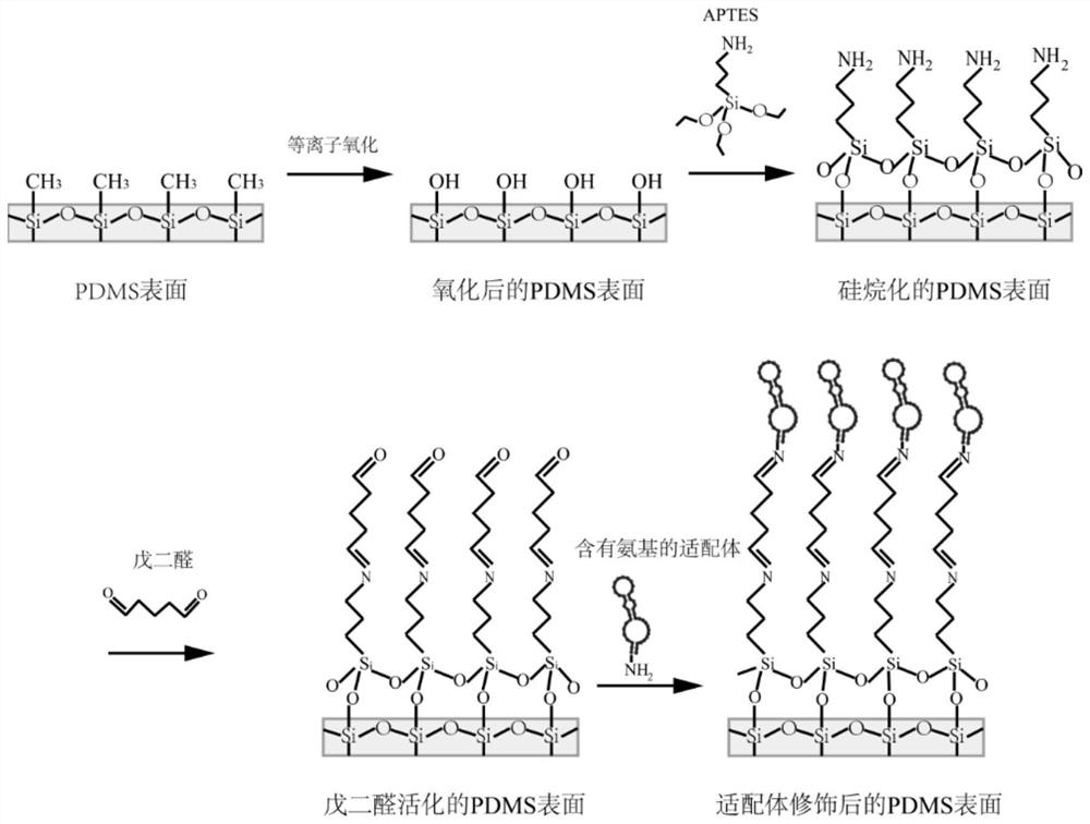
[0062] Preparation method for aptamers containing terminal amination modifications of Escherichia coli O157:H7 pathogenic bacteria: aptamers (aptamers) are composed of DNA or RNA (mainly DNA), smaller than proteins, and enriched by screening Finally, it can have the sensitivity comparable to the antigen-antibody reaction, and at the same time, the synthesis is easier and the stability is better. The sequence structure of the aptamer is obtained through the following documents (Xingkai Hao, Poying Yeh, Yubo Qin, Yuqian Jiang, Zhenyu Qiu, Shuying Li, TaoLe, Xudong Cao, Aptamer surface functionalization of microfluidic devices using dendrimers as multi-handled templates and its application in sensitive detections of foodborne pathogenic bacteria, Analytica Chimica Acta, Volume 1056, 2007, Pages 96-IS-2) The verifications all had good species specificity. Amino groups are directly synthesized at the end of each aptamer for later cross-linking with the modified PMDS. The sequence ...
Embodiment 1
[0064] (1) Preparation of microfluidic chip
[0065] A chip layer with a channel structure is prepared by a mask method, wherein the channel structure has an array structure, the material of the array structure and the material of the chip layer are both PDMS, the chip layer is bonded to the substrate, the substrate is made of glass, and the array structure contains 1000 Each structural unit is cylindrical in shape with a diameter of 20 μm; perpendicular to the direction of fluid flow, the distance between two adjacent structural units is 40 μm; the height of the channel structure and the array structure are both 50 μm; each structure The ratio of the diameter to the height of the unit is 1:2.5, the total horizontal cross-sectional area of the structural unit covers 30% of the horizontal cross-sectional area of the channel structure, and then undergoes plasma oxidation treatment (at room temperature, 300mT, plasma exposure under 20W conditions for 60s), and then Treat with...
Embodiment 2
[0069] (1) Prepare microfluidic chip according to the method of Example 1
[0070] (2) Microfluidic devices
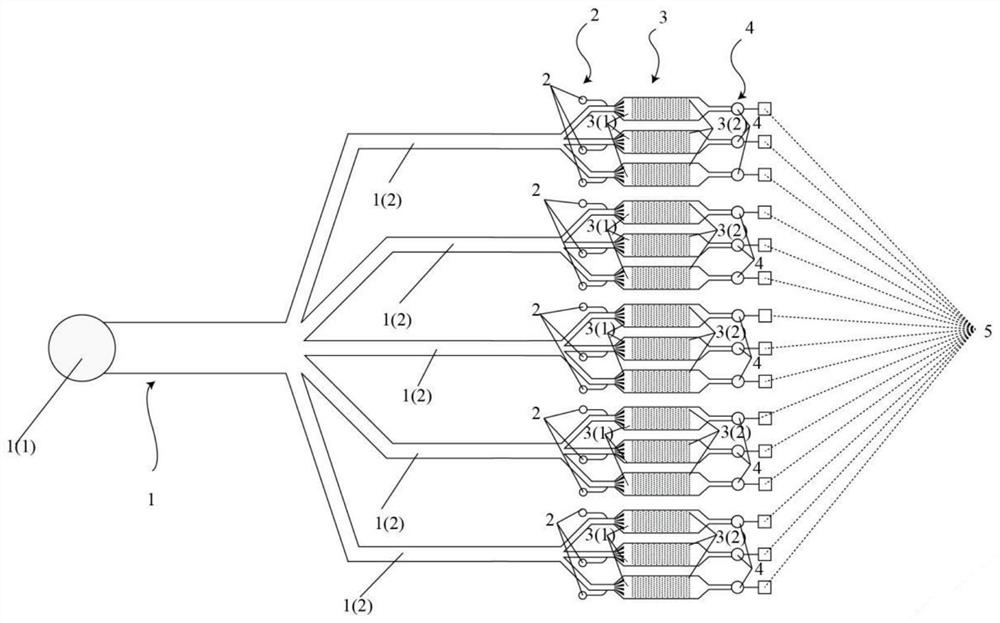
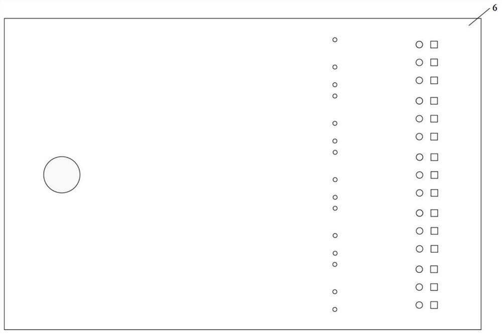
[0071] The microfluidic device includes a sampling unit, and a set of steps connected to the sampling unit in sequence (1) to obtain a microfluidic chip and a detection unit, the outlet of the detection unit is connected to the waste liquid collection unit, and a cover is set on the top of the microfluidic chip (PMMA material), a reagent injection port is provided at the inlet end of each microfluidic chip. The sampling unit includes a sampling port of the sampling unit and a distribution channel of the sampling unit.
[0072] (3) Detection of pathogenic bacteria
[0073] Inject the sample containing Escherichia coli O157:H7 pathogenic bacteria from the inlet 1 (1) of the sampling unit, and pass it into the channel structure of the microfluidic chip, and the sample solution is evenly divided into different channel structures, passing through the structure The aptame...
PUM
| Property | Measurement | Unit |
|---|---|---|
| diameter | aaaaa | aaaaa |
| height | aaaaa | aaaaa |
| height | aaaaa | aaaaa |
Abstract
Description
Claims
Application Information
 - R&D
- Intellectual Property
- Life Sciences
- Materials
- Tech Scout
- Unparalleled Data Quality
- Higher Quality Content
- 60% Fewer Hallucinations
Browse by: Latest US Patents, China's latest patents, Technical Efficacy Thesaurus, Application Domain, Technology Topic, Popular Technical Reports.
© 2025 PatSnap. All rights reserved.Legal|Privacy policy|Modern Slavery Act Transparency Statement|Sitemap|About US| Contact US: help@patsnap.com


