Micro-fluidic chip, preparation method thereof, micro-fluidic device and pathogenic bacterium detection method

A microfluidic chip and microfluidic device technology, applied in biochemical equipment and methods, microbial determination/inspection, measurement devices, etc., can solve the problem of limited ability to capture pathogenic bacteria, slow detection time, complicated operation process, etc. To avoid false positive results, increase the probability of exposure, and efficiently concentrate microorganisms

Active Publication Date: 2020-10-23
TSINGHUA UNIV
View PDF18 Cites 10 Cited by
  • Summary
  • Abstract
  • Description
  • Claims
  • Application Information

AI Technical Summary

Problems solved by technology

Existing detection technologies (microbial testing, immunological testing, and molecular biology techniques, etc.) have their own shortcomings and face many problems: complex operation process, long detection time, low detection target coverage, high false positives, suitable for on-site There are fewer instruments and reagents for detection, etc.
[0004] Existing devices or methods for detecting foodborne pathogenic bacteria using microfluidics have problems such as low species specificity and slow detection time. For example, CN109813695A discloses a microfluidic chip-based microbial detection system and Its detection method, which uses sound waves to separate and enrich bacteria of different diameters, has the problem of poor specificity
[0005] CN107904161A discloses a microfluidic chip for visual real-time detection of pathogen nucleic acid and its preparation method and detection method. It uses immune magnetic beads to capture pathogenic bacteria. Since the immune magnetic beads can only be fixed on the bottom of the chip channel, for The ability to capture pathogenic bacteria in the upper solution is limited, and the capture efficiency of the microfluidic chip of the immunomagnetic beads does not exceed 50%

Method used


Image

  • Micro-fluidic chip, preparation method thereof, micro-fluidic device and pathogenic bacterium detection method
  • Micro-fluidic chip, preparation method thereof, micro-fluidic device and pathogenic bacterium detection method
  • Micro-fluidic chip, preparation method thereof, micro-fluidic device and pathogenic bacterium detection method

Examples


preparation example 1

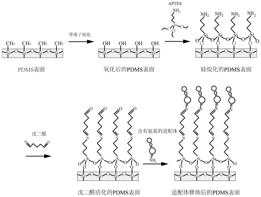
[0062] Preparation method for aptamers containing terminal amination modifications of Escherichia coli O157:H7 pathogenic bacteria: aptamers (aptamers) are composed of DNA or RNA (mainly DNA), smaller than proteins, and enriched by screening Finally, it can have the sensitivity comparable to the antigen-antibody reaction, and at the same time, the synthesis is easier and the stability is better. The sequence structure of the aptamer is obtained through the following documents (Xingkai Hao, Poying Yeh, Yubo Qin, Yuqian Jiang, Zhenyu Qiu, Shuying Li, TaoLe, Xudong Cao, Aptamer surface functionalization of microfluidic devices using dendrimers as multi-handled templates and its application in sensitive detections of foodborne pathogenic bacteria, Analytica Chimica Acta, Volume 1056, 2007, Pages 96-IS-2) The verifications all had good species specificity. Amino groups are directly synthesized at the end of each aptamer for later cross-linking with the modified PMDS. The sequence ...

Embodiment 1

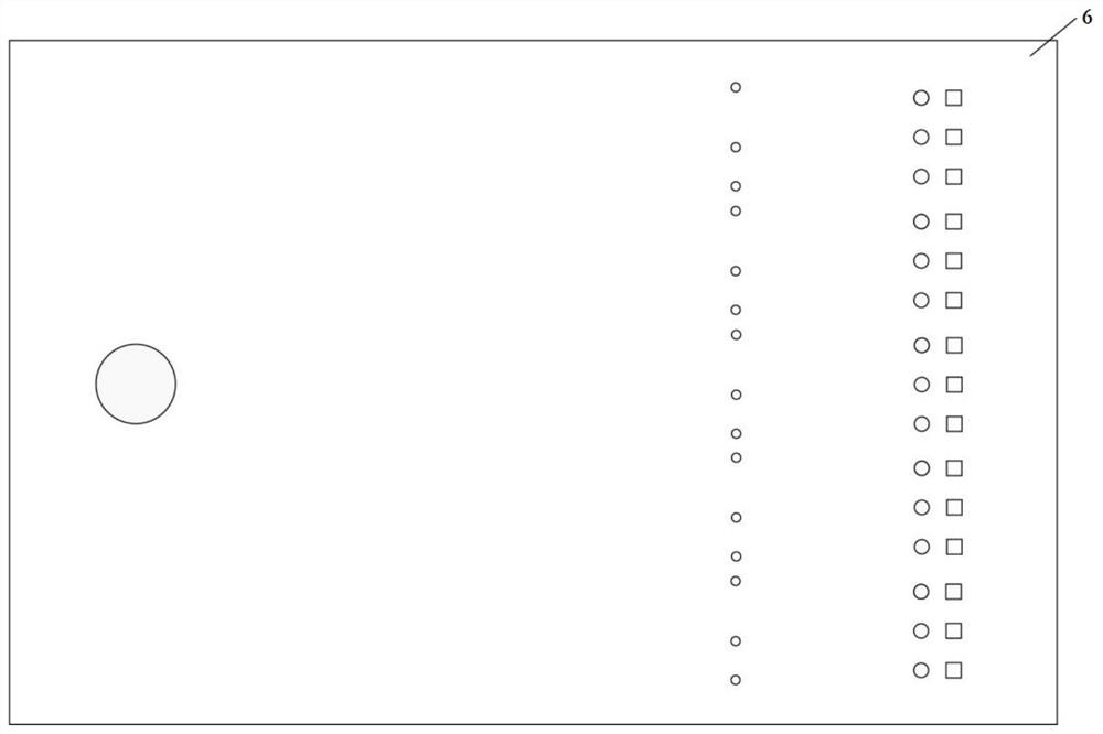
[0064] (1) Preparation of microfluidic chip

[0065] A chip layer with a channel structure is prepared by a mask method, wherein the channel structure has an array structure, the material of the array structure and the material of the chip layer are both PDMS, the chip layer is bonded to the substrate, the substrate is made of glass, and the array structure contains 1000 Each structural unit is cylindrical in shape with a diameter of 20 μm; perpendicular to the direction of fluid flow, the distance between two adjacent structural units is 40 μm; the height of the channel structure and the array structure are both 50 μm; each structure The ratio of the diameter to the height of the unit is 1:2.5, the total horizontal cross-sectional area of ​​the structural unit covers 30% of the horizontal cross-sectional area of ​​the channel structure, and then undergoes plasma oxidation treatment (at room temperature, 300mT, plasma exposure under 20W conditions for 60s), and then Treat with...

Embodiment 2

[0069] (1) Prepare microfluidic chip according to the method of Example 1

[0070] (2) Microfluidic device

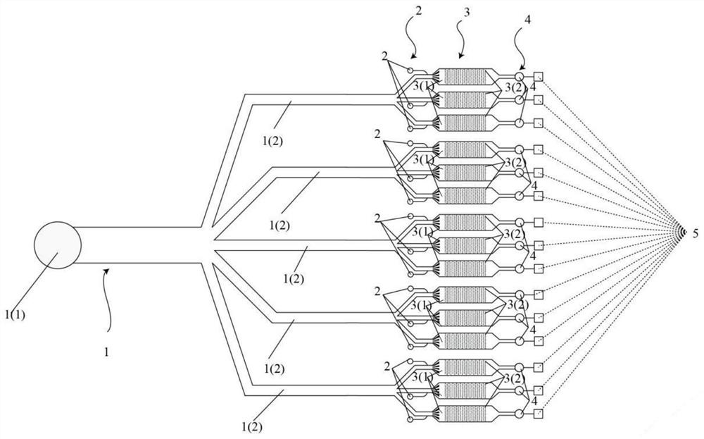
[0071] The microfluidic device includes a sampling unit, and a set of steps connected to the sampling unit in sequence (1) to obtain a microfluidic chip and a detection unit, the outlet of the detection unit is connected to the waste liquid collection unit, and a cover is set on the top of the microfluidic chip (PMMA material), a reagent injection port is provided at the inlet end of each microfluidic chip. The sampling unit includes a sampling port of the sampling unit and a distribution channel of the sampling unit.

[0072] (3) Detection of pathogenic bacteria

[0073] Inject the sample containing Escherichia coli O157:H7 pathogenic bacteria from the inlet 1 (1) of the sampling unit, and pass it into the channel structure of the microfluidic chip, and the sample solution is evenly divided into different channel structures, passing through the structure The aptamer...


PUM

PropertyMeasurementUnit
diameteraaaaaaaaaa
heightaaaaaaaaaa
heightaaaaaaaaaa

Abstract

The invention discloses a micro-fluidic chip, a preparation method thereof, a micro-fluidic device and a pathogenic bacteria detection method. The micro-fluidic chip comprises a chip layer, a channelstructure is arranged in the chip layer, and an array structure of which the surface is modified with an aptamer is arranged in the channel structure. The micro-fluidic device prepared by adopting themicro-fluidic chip can be used for rapid and high-sensitivity detection of pathogenic bacteria in food, and the detection effect is high in stability.

Description

technical field [0001] The invention relates to a microfluidic chip and a preparation method thereof, a microfluidic device, and a detection method of pathogenic bacteria. Background technique [0002] Food poisoning caused by foodborne pathogenic microorganisms is a food safety issue of global concern. According to the estimates of the World Health Organization, more than 70% of the annual food-borne diseases in the world are caused by pathogenic microorganisms. In recent years, according to statistics from the National Health and Family Planning Office and the National Center for Disease Control and Prevention, the number of food poisoning caused by pathogenic microorganisms has always ranked first in food poisoning incidents. China is the largest food consumer, producer and importer. It is an urgent task for us to improve the detection level of food-borne pathogenic microorganisms and the ability to respond to food safety emergencies. Fast-reading, accurate and sensitiv...

Claims


Application Information

Patent Timeline
Patent Type & Authority Applications(China)
IPC IPC(8): B01L3/00C12Q1/04G01N21/64G01N21/76
CPCB01L3/502707B01L3/502761B01L2200/021B01L2200/10B01L2300/02B01L2300/0864B01L2300/0887B01L2300/12C12Q1/04G01N21/64G01N21/763
Inventor 林金明陈建李海芳林玲
Owner TSINGHUA UNIV
Why Eureka
Try Eureka