Impact fatigue performance evaluation test machine for presser foot material of sewing machine

A technique for evaluating test and impact fatigue, applied in the field of sewing machinery manufacturing

Pending Publication Date: 2019-10-22
YANSHAN UNIV
View PDF0 Cites 0 Cited by
  • Summary
  • Abstract
  • Description
  • Claims
  • Application Information

AI Technical Summary

Problems solved by technology

At present, there is a lack of test equipment to simulate the complex working conditions of sewing machines and evaluate the fatigue performance of the surface coating of sewing machine presser foot materials under high-frequency impact conditions

Method used


Image

  • Impact fatigue performance evaluation test machine for presser foot material of sewing machine
  • Impact fatigue performance evaluation test machine for presser foot material of sewing machine
  • Impact fatigue performance evaluation test machine for presser foot material of sewing machine

Examples


Embodiment Construction

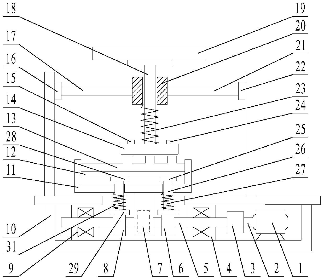
[0013] figure 1 It is a structural schematic diagram of a testing machine for evaluating the impact fatigue performance of sewing machine presser foot materials disclosed in the present invention. The testing machine can detect Damage to the coating on the surface of the sewing machine presser foot material.

[0014] The presser foot material loading system includes a presser foot material 14, a beam I17, a pressing rod I18, a pressure block I19, a guide sleeve 20, a beam II21 and a spring I23. The pressure block I19 is fixedly connected with the pressure rod I18 through the thread pair, the pressure rod I18 moves in the guide sleeve 20, the spring I23 is installed on the pressure rod I18, and is located between the guide sleeve 20 and the presser foot material 14, the presser foot material 14 It is fixedly connected with the pressure rod I18 through the thread pair.

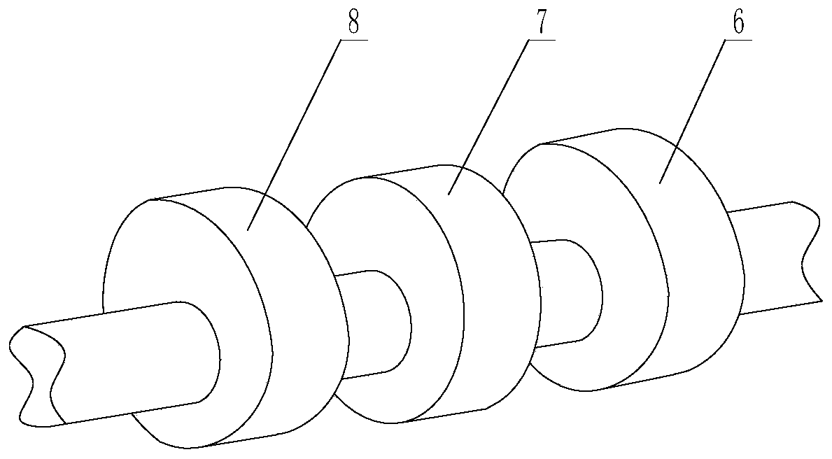
[0015] The feed dog transmission system includes motor 1, motor shaft 2, coupling 3, bearing housing Ⅰ4, ca...


PUM


Abstract

The invention relates to an impact fatigue performance evaluation test machine for a presser foot material of a sewing machine. A presser foot material loading system, a feeding transmission system, and a detection system are arranged on the test machine. The feeding transmission system simulates the actual movement of the feeding unit by a camshaft (5) and other mechanisms. An acoustic emission sensor (15) and a temperature sensor (24) are fixed on a presser foot material (14) by screws. A pressure sensor I (16) and a pressure sensor II (22) are fixed on inner walls of the two sides of a frame (10) by screws. Signals of the acoustic emission sensor (15), the temperature sensor (24), the pressure sensor I (16) and the pressure sensor II (22) are transmitted to a computer for processing bya data acquisition card. According to the invention, the actual movement of the feeding unit is simulated to realize reliability evaluation of the surface coating of the presser foot material under the high-frequency impact condition.

Description

technical field [0001] The invention relates to the field of sewing machinery manufacturing, in particular to a testing machine for evaluating the impact fatigue performance of sewing machine presser foot materials. Background technique [0002] The presser foot is an important part of the sewing machine, and its anti-friction and wear-resisting properties play a vital role in the stability of the fabric stitches. Presser foot manufacturers usually coat the surface of the presser foot to reduce its friction. So that the cloth can be fed smoothly. Using the forming presser foot to test will cause unnecessary waste, so it is a relatively simple and effective method to directly test the presser foot material. This method does not need to shape the presser foot material, and can directly perform coating treatment on the surface of the presser foot material, and verify whether the surface treatment method of the presser foot material meets the expected wear-reducing and wear-res...

Claims


Application Information

Patent Timeline
Patent Type & Authority Applications(China)
IPC IPC(8): G01N3/32G01N3/02G01N3/06
CPCG01N3/32G01N3/02G01N3/06G01N2203/0008G01N2203/001G01N2203/0062G01N2203/0282G01N2203/0658G01N2203/0676G01N2203/0694
Inventor 齐效文卢改粉孙红亮王海张文力
Owner YANSHAN UNIV
Why Eureka
Try Eureka