Z-direction high-resolution CT scanning mode and image reconstruction method

An image reconstruction and CT scanning technology, applied in the field of medical imaging, can solve the problems of low-density resolution reduction, scan FOV reduction, scale increase, etc., to achieve the effect of z-direction resolution improvement and aliasing artifacts reduction

Active Publication Date: 2019-10-22
四川明峰医疗科技有限公司
View PDF7 Cites 2 Cited by
  • Summary
  • Abstract
  • Description
  • Claims
  • Application Information

AI Technical Summary

Problems solved by technology

[0006]1. Reducing the size of the detector pixels in the z direction will lead to an increase in the ratio of the gap between the detector rows to the total detector area, so the detector geometry Reduced efficiency results in increased image noise and reduced resolution at low densities
[0007]2. Using a special helical scanning pitch can increase the z-direction sampling rate, but the effective range of this measure is small in the scanning plane, that is, in the plane where the rays are effectively interlaced Scan FOV reduction
However, in order to reduce the aliasing artifacts caused by sampling in the angular direction of the plane, the number of samples required for each focal point to rotate one revolution of the rack is limited. Using 4 focal points will cause the number of samples to be increased by 4 times. The data transmission of the slip ring and the consumption of computing resources for reconstruction are great challenges, and the technical difficulty is greatly increased, so the cost will be greatly increased

Method used


Image

  • Z-direction high-resolution CT scanning mode and image reconstruction method
  • Z-direction high-resolution CT scanning mode and image reconstruction method
  • Z-direction high-resolution CT scanning mode and image reconstruction method

Examples


Embodiment Construction

[0033] In order to make the technical means of the present invention and its achievable technical effects more clearer and more complete, the following embodiments are provided, and the following detailed descriptions are made in conjunction with the drawings:

[0034] A z-direction high-resolution CT scanning method and image reconstruction method of this embodiment,

[0035] Among them, z-direction high-resolution CT scanning methods include the following:

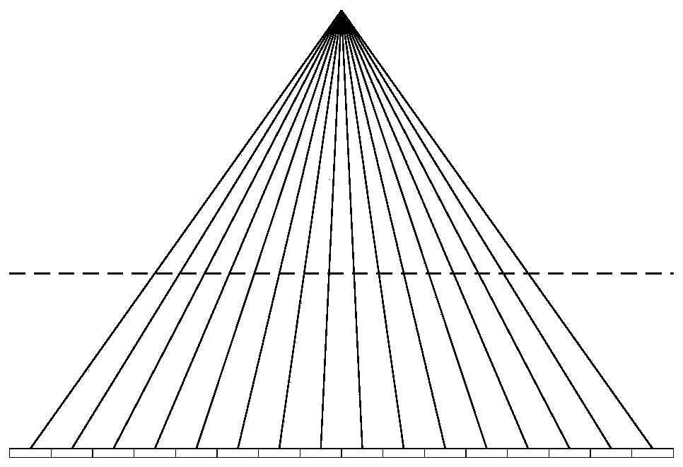
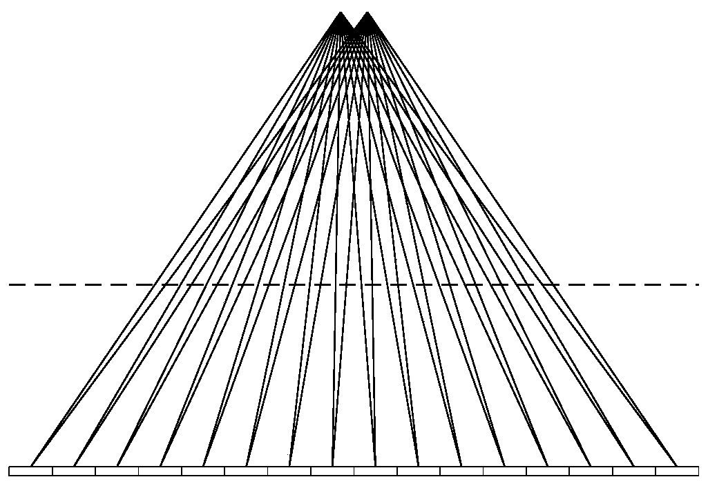
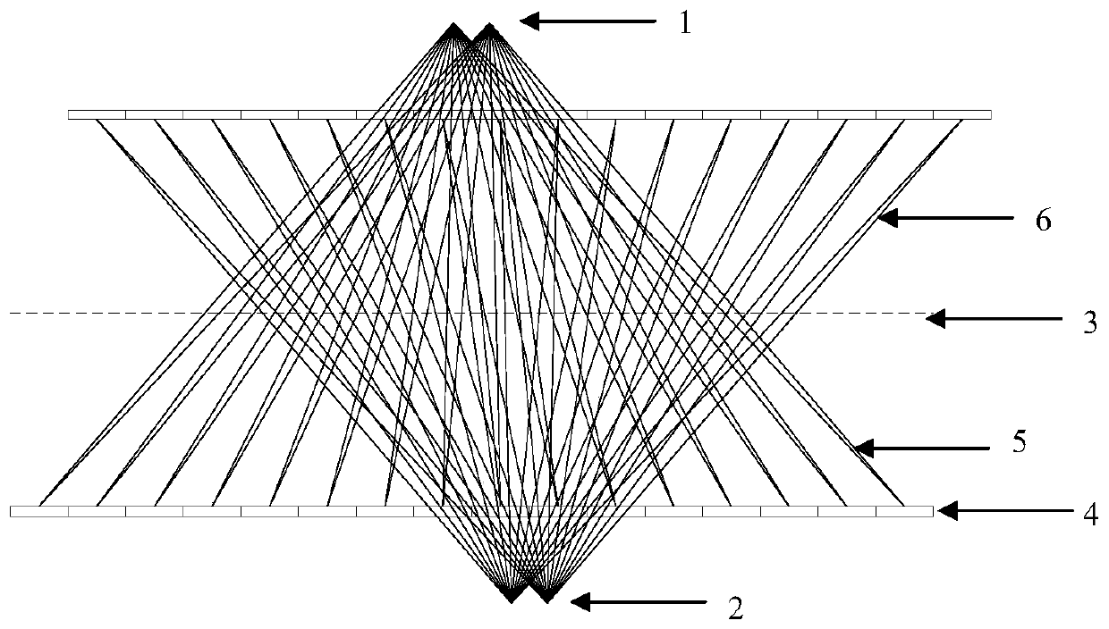
[0036] (1) Z-direction flying focus sampling: two adjacent samples adopt two different focal points, and two sets of chief rays from the focal point to the pixel center of the detector unit are obtained correspondingly; during the rotation of the gantry, the odd-numbered samples correspond to One focus gets sample group one, and even-numbered samples correspond to another focus to get sample group two. In the steps of the z-flying focus scanning mode, the phase position of the patient bed and the tube remains unchanged during ...


PUM


Abstract

The invention provides a z-direction high-resolution CT scanning mode and an image reconstruction method, and relates to the technical field of medical image. The z-direction high-resolution CT scanning mode comprises the steps that z-direction flying focus sampling is conducted, the positions of every two adjacent focuses are adjusted, the optimal pitch is selected, and a rack shaft is rotated by180 degrees in a spiral scanning mode; the image reconstruction method comprises the following steps of: respectively rearranging the data of the two focuses; arranging the data to form two parallelbeams, performing interpolation in an angle direction, enabling scanning data angles of two flying focuses to be the same, performing interpolation in a radial direction, enabling non-equidistant parallel beams of the two focuses to be changed into equidistant parallel beams, performing filtering operation on the two parallel beams respectively, and performing back projection calculation. The technology of switching between the two focuses in the z direction is combined with the special spiral scanning screw pitch, so that the four-time sampling rate in the z direction is achieved, aliasing artifacts are reduced, and the resolution in the z direction is improved.

Description

Technical field [0001] The invention relates to the technical field of medical imaging, in particular to a z-direction high-resolution CT scanning method and an image reconstruction method. Background technique [0002] The main components of the third-generation CT system include Tube (tube), Collimator (beam limiter), Detector (detector). The X-ray tube emits X-rays, which are restricted by the beam limiter to form a cone-shaped beam. The cone beam is irradiated on the detector, converted into electrical signals by the detector, and converted into digital information by the data acquisition and conversion unit, and stored in the image processing system. The image processing system undergoes a series of correction algorithms and image reconstruction algorithms to generate images and display them on the monitor. In terms of cost and technological maturity, mainstream detectors have adopted a large number of detector modules arranged on an arc or polygonal surface to form the en...

Claims


Application Information

Patent Timeline
Patent Type & Authority Applications(China)
IPC IPC(8): G06T11/00A61B6/03A61B6/00
CPCG06T11/006G06T11/005A61B6/032A61B6/52G06T2211/421
Inventor 王斌王瑶法黄俊杰陈婷
Owner 四川明峰医疗科技有限公司
Why Eureka
Try Eureka