Shifting register and driving method thereof, gate driving circuit and display device

A shift register and gate technology, applied in the field of gate drive circuits, shift registers and driving methods thereof, and display devices, can solve the problems of no output, horizontal stripes, screen scanning, threshold voltage shift and the like

Active Publication Date: 2019-10-22
BOE TECH GRP CO LTD +1
View PDF13 Cites 7 Cited by
  • Summary
  • Abstract
  • Description
  • Claims
  • Application Information

AI Technical Summary

Problems solved by technology

[0003] However, in practical applications, since the gate of the thin film transistor in the shift register is subjected to various voltage signals for a long time, the threshold voltage will shift, resulting in attenuation of various signals or even no output.
Since the shift registers are cascaded, if there is no output in one stage of the shift register, it will cause abnormal output phenomena such as multi-output (Multi-Output) in the other stage of the shift register, and eventually lead to A variety of display problems, such as horizontal stripes on the screen, screen scanning, etc.

Method used


Image

  • Shifting register and driving method thereof, gate driving circuit and display device
  • Shifting register and driving method thereof, gate driving circuit and display device
  • Shifting register and driving method thereof, gate driving circuit and display device

Examples


Embodiment Construction

[0059] Specific embodiments of the present invention will be described in detail below in conjunction with the accompanying drawings. It should be understood that the specific embodiments described here are only used to illustrate and explain the present invention, and are not intended to limit the present invention.

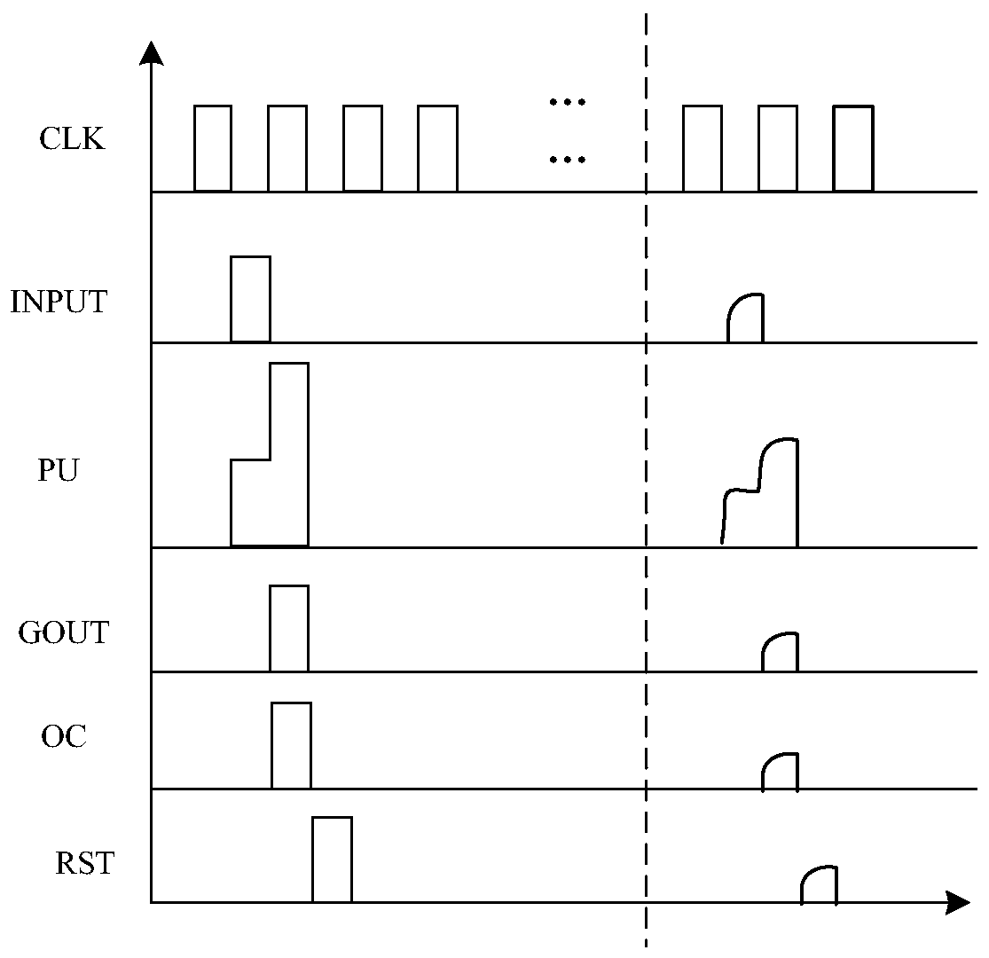
[0060] In the gate drive circuit, multiple shift registers are cascaded to realize sequential output. However, since the gate of the thin film transistor in the shift register is subjected to various voltage signals for a long time, the threshold voltage will shift, resulting in attenuation of various signals or even no output. figure 1 It is a signal timing diagram before and after signal attenuation of a certain shift register unit in the gate drive circuit of the prior art. The left side of the dotted line is the timing of the signal of the shift register under normal conditions, and the right side of the dotted line is the transistor of the shift register. ...


PUM


Abstract

The invention provides a shift register, which comprises: a pre-charging circuit which is used for pre-charging a pull-up node under the control of an effective signal provided by an input end; a reset circuit which is used for transmitting the signal provided by the first power supply end to the pull-up node under the control of the effective signal provided by the reset end; a first output circuit which is used for transmitting a signal of a clock signal end to a first output end when the pull-up node is at an effective potential; a second output circuit which is used for transmitting the signal of the clock signal end to the second output end when the pull-up node is at the effective potential; and an output control circuit which is used for conducting the first output end and the second output end under the control of the effective signal provided by the output control end. The invention further provides a driving method of the shift register, a gate driving circuit and a display device. According to the invention, poor display caused by threshold drift of the transistor can be reduced.

Description

technical field [0001] The invention relates to the field of display technology, in particular to a shift register, a driving method thereof, a gate driving circuit, and a display device. Background technique [0002] Gate Driver On Array (GOA for short) is a technology for integrating a gate driver circuit on an array substrate. The gate driver circuit includes a plurality of shift registers, and each shift register corresponds to a row of gate lines. [0003] However, in practical applications, since the gate of the thin film transistor in the shift register is subjected to various voltage signals for a long time, the threshold voltage will shift, resulting in attenuation of various signals or even no output. Since the shift registers are cascaded, if there is no output in one stage of the shift register, it will cause abnormal output phenomena such as multi-output (Multi-Output) in the other stage of the shift register, and eventually lead to A variety of display problem...

Claims


Application Information

Patent Timeline
Patent Type & Authority Applications(China)
IPC IPC(8): G09G3/20G11C19/28
CPCG09G3/20G09G2310/0286G11C19/28
Inventor 李佑路贺之洋王慧
Owner BOE TECH GRP CO LTD
Why Eureka
Try Eureka