
Rotor core, rotor, rotor assembly and motor

A rotor core and rotor core technology, applied in the direction of electric components, magnetic circuit rotating parts, electrical components, etc., can solve the problem that it is difficult to adjust the dynamic balance to meet the requirements, it is difficult to ensure the accuracy of dynamic balance, waste of time and personnel, etc. question

Active Publication Date: 2019-10-22
GUANDONG MEDIA INTELLIGENT TECH CO LTD
View PDF5 Cites 0 Cited by
  • Summary
  • Abstract
  • Description
  • Claims
  • Application Information

AI Technical Summary

Problems solved by technology

On the basis of not changing the rotor structure, it is difficult to adjust the dynamic balance to meet the requirements. Often the same rotor needs to be adjusted multiple times to meet the accuracy requirements, resulting in a waste of time and personnel. At the same time, it is difficult to guarantee the dynamic balance accuracy.

Method used


Image

  • Rotor core, rotor, rotor assembly and motor
  • Rotor core, rotor, rotor assembly and motor
  • Rotor core, rotor, rotor assembly and motor

Examples


Embodiment Construction

[0034] Specific embodiments of the present invention will be described in detail below in conjunction with the accompanying drawings. It should be understood that the specific embodiments described here are only used to illustrate and explain the present invention, and are not intended to limit the present invention.

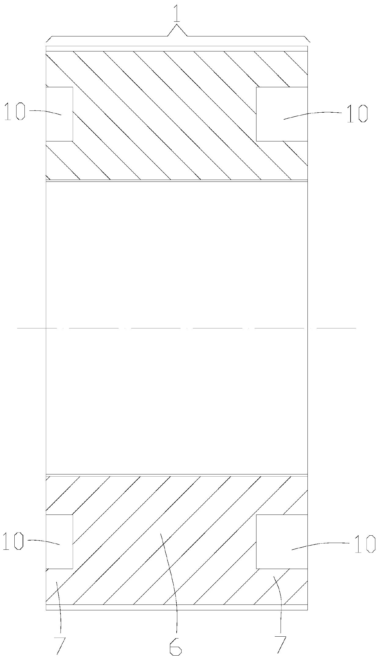
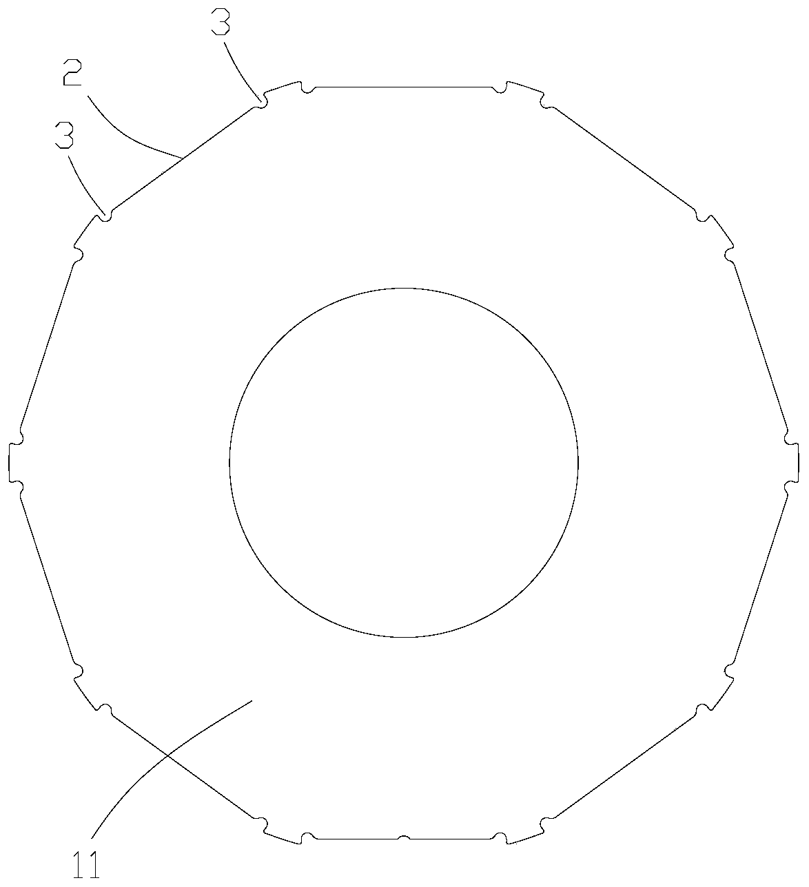
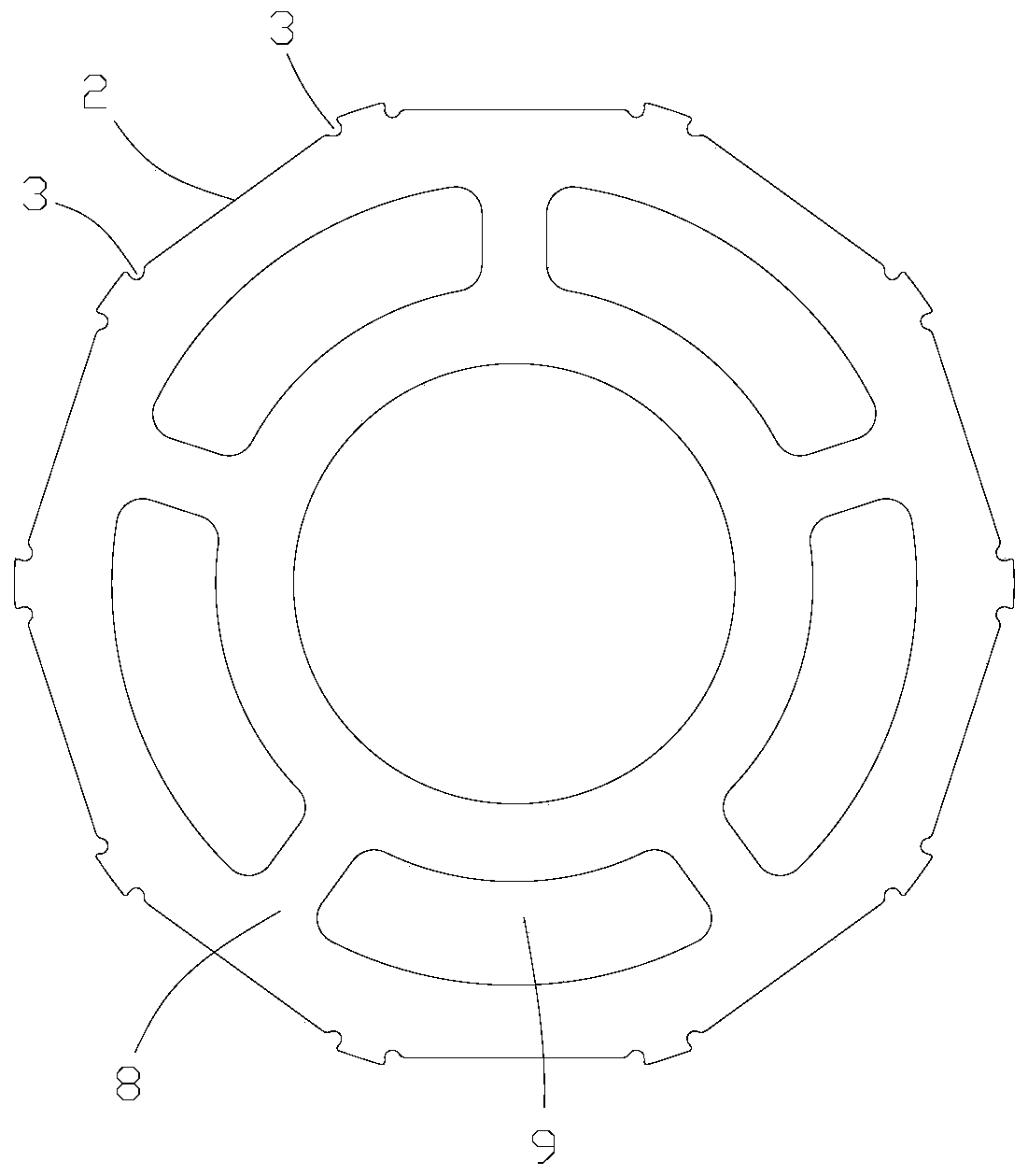
[0035] refer to figure 1 , image 3 as well as Figure 15 A rotor core 1 provided by the present invention includes a first rotor core 6 and second rotor cores 7 respectively arranged on both axial sides of the first rotor core 6 in the axial direction of the rotor core, Wherein, the second rotor core 7 includes a plurality of second rotor punches 8 that can be accessed and stacked in the axial direction, that is, the second rotor punches 8 can be accessed and placed according to actual needs to adjust the second rotor punches 8 A plurality of circumferentially spaced openings 9 are formed on each second rotor punching piece 8 , and the openings 9 on the stac...


PUM


Abstract

The invention relates to the technical field of motors, and discloses a rotor core, a rotor, a rotor assembly and a motor. The rotor core includes a first rotor core body and second rotor core bodiesrespectively disposed on both sides of the first rotor core body in an axial direction of the rotor core, wherein the second rotor core body includes a plurality of second rotor punching sheets capable of being taken and placed and axially stacked, each second rotor punching sheet is provided with a plurality of circumferentially spaced openings, the openings in the plurality of stacked second rotor punching sheets form axially extending dynamic balance body placement space of the second rotor core body. After the rotor core is disposed on a rotating shaft, the number of the second rotor punching sheets on both sides of the first rotor core body can be adjusted correspondingly, a rotor such as a large-outer diameter and short-axis length can be changed to an easy-to-adjust dynamic balanceassembly at an initial motor manufacturing stage, the time can be saved, and the dynamic balance adjustment precision is improved.

Description

technical field [0001] The present invention relates to the technical field of motors, in particular to a rotor core, a rotor, a rotor assembly and a motor. Background technique [0002] The rotor of the motor is arranged on the rotating shaft, and the rotating shaft is arranged on the motor housing through the bearings at both ends, so that the rotation of the rotor drives the rotating shaft to rotate, thereby outputting the rotating power. The motor will vibrate during actual operation. [0003] The unbalanced rotor is one of the main causes of excessive vibration and noise of the motor, which will directly affect the working performance and service life of the motor. Therefore, it is very necessary to adjust the dynamic balance of the rotor. At present, there are mainly two ways to adjust the dynamic balance of the rotor, one is to remove weight, and the other is to increase weight. Regardless of adding weight or removing weight, it is necessary to find the dynamic and...

Claims


Application Information

Patent Timeline
Patent Type & Authority Applications(China)
IPC IPC(8): H02K1/27H02K7/00
CPCH02K1/278H02K7/003
Inventor 赵丽丹丁伟兵
Owner GUANDONG MEDIA INTELLIGENT TECH CO LTD
Learn More