
Heat treatment oily fume purifying device

A technology of oil fume purification and suction pipe, which is applied in the direction of gas treatment, filtration treatment, sedimentation treatment, etc., can solve the problems of inability to adjust the position of oil suction fume, reduce the effect of smoking, increase resource consumption, etc., to increase the effect of waste gas treatment, The effect of increasing the effect and reducing the consumption of water resources

Active Publication Date: 2019-10-25
嘉兴金凌五金科技股份有限公司
View PDF7 Cites 4 Cited by
  • Summary
  • Abstract
  • Description
  • Claims
  • Application Information

AI Technical Summary

Problems solved by technology

[0004] The purpose of the present invention is to provide a heat treatment oil fume purification device to solve the problem in the above background technology that the heat treatment oil fume cannot be adjusted in the position of the oil suction fume during the treatment process, thereby reducing the overall smoking effect, and most of the heat treatment oil fumes are only treated with oil fume. However, the irritating odor contained in the exhaust gas cannot be treated, resulting in a certain odor in the discharged gas, which reduces the overall practicability, and the heat treatment oil fume will be continuously sprayed with water during the purification process, thereby increasing the The overall resource consumption problem

Method used


Image

  • Heat treatment oily fume purifying device
  • Heat treatment oily fume purifying device
  • Heat treatment oily fume purifying device

Examples


Embodiment Construction

[0021] The following will clearly and completely describe the technical solutions in the embodiments of the present invention with reference to the accompanying drawings in the embodiments of the present invention. Obviously, the described embodiments are only some, not all, embodiments of the present invention. Based on the embodiments of the present invention, all other embodiments obtained by persons of ordinary skill in the art without making creative efforts belong to the protection scope of the present invention.

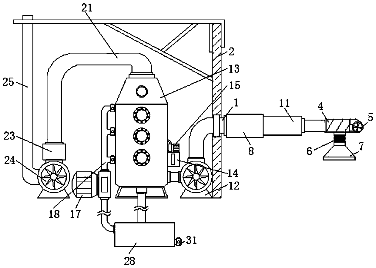
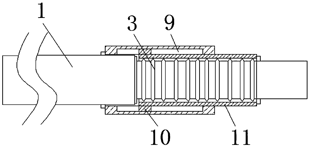
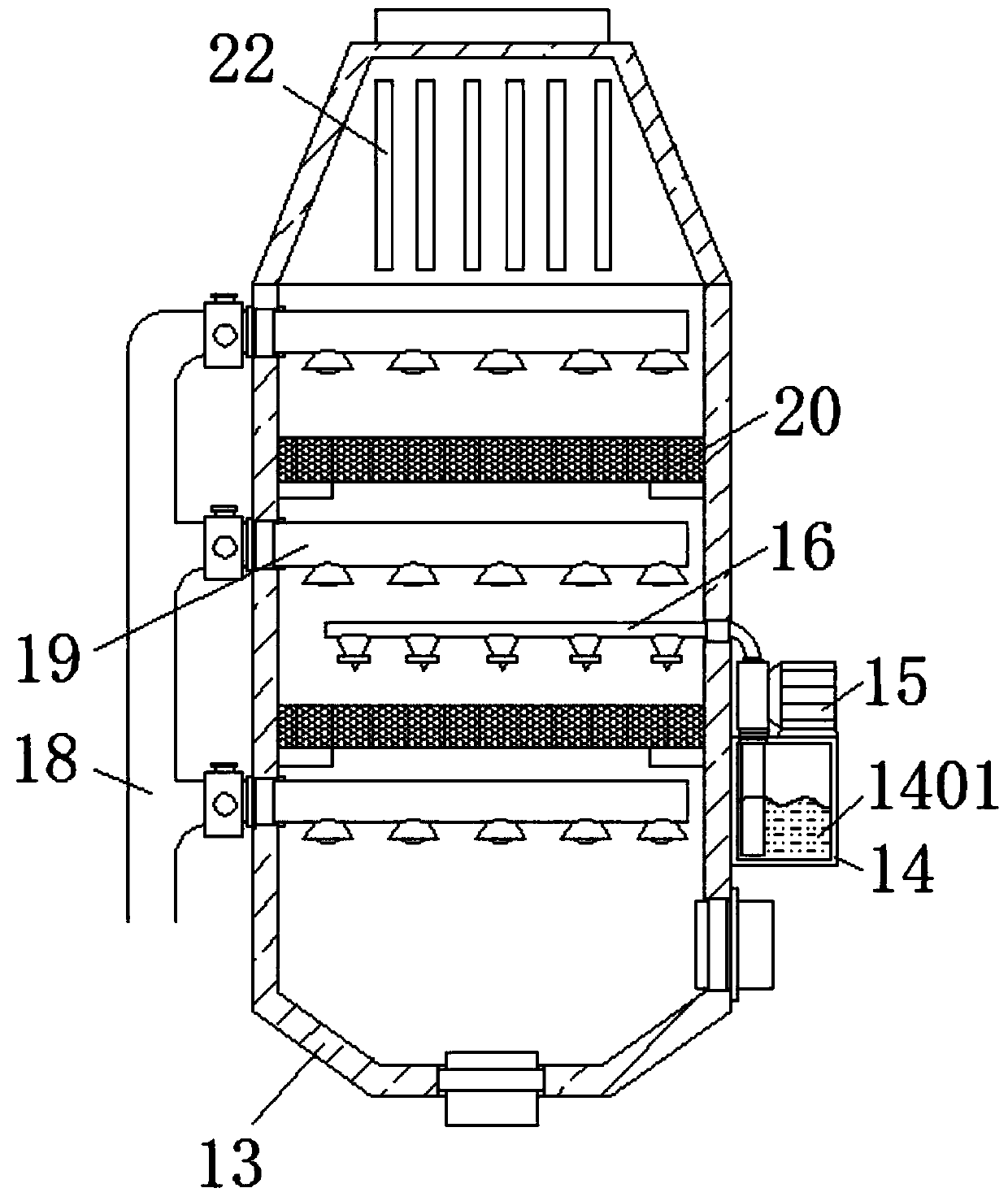
[0022] see Figure 1-6 , the present invention provides a technical solution: a heat treatment oil fume purification device, including a suction pipe 1, a wall 2 is fixedly connected to the outside of the suction pipe 1, and the suction pipe 1 extends through the wall 2 to the right end of the wall 2, and the suction pipe 1 The right end of the air pipe 1 is fixedly connected with the first telescopic bellows 3, and the right side of the first telescopic bello...


PUM


Abstract

The invention discloses a heat treatment oily fume purifying device. The heat treatment oily fume purifying device comprises a gas suction pipe, the outer side of the gas suction pipe is fixedly connected with a wall, the gas suction pipe penetrates through the wall to extend to the right end of the wall, the right end of the gas suction pipe is fixedly connected with a first telescopic corrugatedpipe, a water outlet of a spraying tank is fixedly connected with a settling pond through a pipeline, the settling pond is fixedly connected with a water suction opening of a second water pump through a pipeline, the upper end inside the settling pond is fixedly connected with a mounting plate, a floating ball liquid level device is fixedly mounted inside the mounting plate, and the lower end ofthe settling pond is fixedly connected with an oil discharging pipe. According to the heat treatment oily fume purifying device, the overall spraying effect is improved, consumption of water resourcesis reduced, an undesirable odor in filtered gas is improved through shell activated carbon with the iodine value being 1000, the discharged gas is kept dry, thus the overall waste gas treatment effect is improved, and overall practicability is improved.

Description

technical field [0001] The invention relates to the technical field of oil fume purification, in particular to a heat treatment oil fume purification device. Background technique [0002] Oil fumes often appear during heat treatment, and the high-concentration oil-fume exhaust gas emitted will cause great harm to the air and the human body. The gas will not cause harm to the air and human body, and the oily waste gas will be discharged after reaching the standard. [0003] However, the heat-treated oil fume cannot be adjusted in the position of the oil-absorbing fume during the treatment process, thereby reducing the overall smoking effect, and most of the heat-treated oil fume is only treated with oil fume, and the pungent odor contained in the exhaust gas cannot be treated, resulting in exhausted gas It will have a certain smell, which reduces the overall practicability, and the heat treatment oil fume will be continuously sprayed with water during the purification proces...

Claims


Application Information

Patent Timeline
Patent Type & Authority Applications(China)
IPC IPC(8): B01D47/06B01D53/02B01D53/26B01D53/78B01D53/40B01D36/04C02F9/02C02F103/18
CPCB01D36/04B01D47/06B01D53/02B01D53/26B01D53/40B01D53/78B01D2253/102B01D2257/80B01D2258/0283C02F1/001C02F1/52C02F2001/007C02F2103/18
Inventor 张小林
Owner 嘉兴金凌五金科技股份有限公司
Learn More