Cleaning device and substrate cleaning method
A technology for cleaning devices and substrates, applied in cleaning methods and appliances, cleaning methods using liquids, cleaning methods using tools, etc., can solve problems such as easy slipping of substrates, poor cleaning effect, etc., to solve liquid backflow and improve cleaning effect of effect
- Summary
- Abstract
- Description
- Claims
- Application Information
AI Technical Summary
Problems solved by technology
Method used
Image
Examples
Embodiment 1
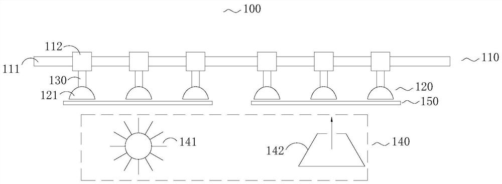
[0035] The embodiment of the present disclosure provides a cleaning device, which is combined with figure 1 Describe in detail.
[0036] like figure 1 as shown, figure 1 A schematic structural diagram of a cleaning device 100 provided in an embodiment of the present disclosure. The cleaning device 100 includes a driving part 110 , a grabbing part 120 , a telescoping rod 130 and a cleaning part 140 .
[0037] Specifically, the driving part 110 includes a driving motor (not shown in the figure), a guide rail 111 and a plurality of sliders 112 arranged at intervals on the guide rail 111, and the driving motor drives the plurality of sliders 112 on the 111 runs on the guide rail.
[0038] In this embodiment, the guide rail 111 is an annular guide rail, and the drive mode of the driving part 110 is a synchronous belt drive. In some other embodiments, the driving mode of the driving part 110 is not limited to synchronous belt driving, and may also be chain driving or screw driv...
Embodiment 2
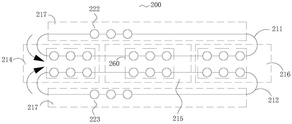
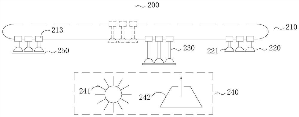
[0046] The present disclosure provides a cleaning device, combined with Figure 2 to Figure 3 Describe in detail.
[0047] like figure 2 and image 3 as shown, figure 2 It is a schematic top view structure diagram of the cleaning device 200 provided by the embodiment of the present disclosure, image 3 A schematic side view of the structure of the cleaning device 200 provided by the embodiment of the present disclosure, the cleaning device 200 includes a driving part 210, a gripping part 220, and a plurality of telescopic rods 230
[0048] The driving part 210 includes a driving motor (not shown), a guide rail and a plurality of sliders 213 arranged at intervals on the guide rail, and the guide rail includes a first guide rail 211 and a second guide rail 212 arranged in parallel. When the slider 213 runs, the speed of the slider 213 on the first guide rail 211 and the second guide rail 212 is the same, and the running direction is opposite. because image 3 It is a sid...
Embodiment 3
[0060] The embodiment of the present disclosure provides a cleaning device, which is combined with Figure 4 to Figure 5 Describe in detail.
[0061] like Figure 4 and Figure 5 as shown, Figure 4 A schematic top view of the cleaning device 300 provided in the disclosed embodiment, Figure 5 A schematic side view of the structure of the cleaning device 300 provided by the embodiment of the present disclosure. The cleaning device 300 includes a driving part 310, a grabbing part 320, a plurality of telescopic rods 330
[0062] The driving part 310 includes a driving motor (not shown), a guide rail and a plurality of sliders 313 arranged at intervals on the guide rail, and the guide rail includes a first guide rail 311 and a second guide rail 312 arranged in parallel, so The running speed of the slider 313 on the first guide rail 311 and the second guide rail 312 is the same, and the running direction is opposite.
[0063] In this embodiment, the guide rail is an annular ...
PUM
 Abstract
Description
Claims
Application Information
 - R&D
- Intellectual Property
- Life Sciences
- Materials
- Tech Scout
- Unparalleled Data Quality
- Higher Quality Content
- 60% Fewer Hallucinations
Browse by: Latest US Patents, China's latest patents, Technical Efficacy Thesaurus, Application Domain, Technology Topic, Popular Technical Reports.
© 2025 PatSnap. All rights reserved.Legal|Privacy policy|Modern Slavery Act Transparency Statement|Sitemap|About US| Contact US: help@patsnap.com


