Plate withdrawing mechanism with stable and efficient separation
An efficient and stable technology, which is applied in the direction of conveyor objects, ceramic molding machines, and object unsealing, can solve the problems of high labor intensity in the separation of plates and bricks, limit the recycling of pallets, and affect the efficiency of brick stacking, etc., to improve Efficiency of board removal, satisfactory recycling, convenient and quick operation
- Summary
- Abstract
- Description
- Claims
- Application Information
AI Technical Summary
Problems solved by technology
Method used
Image
Examples
Embodiment 1
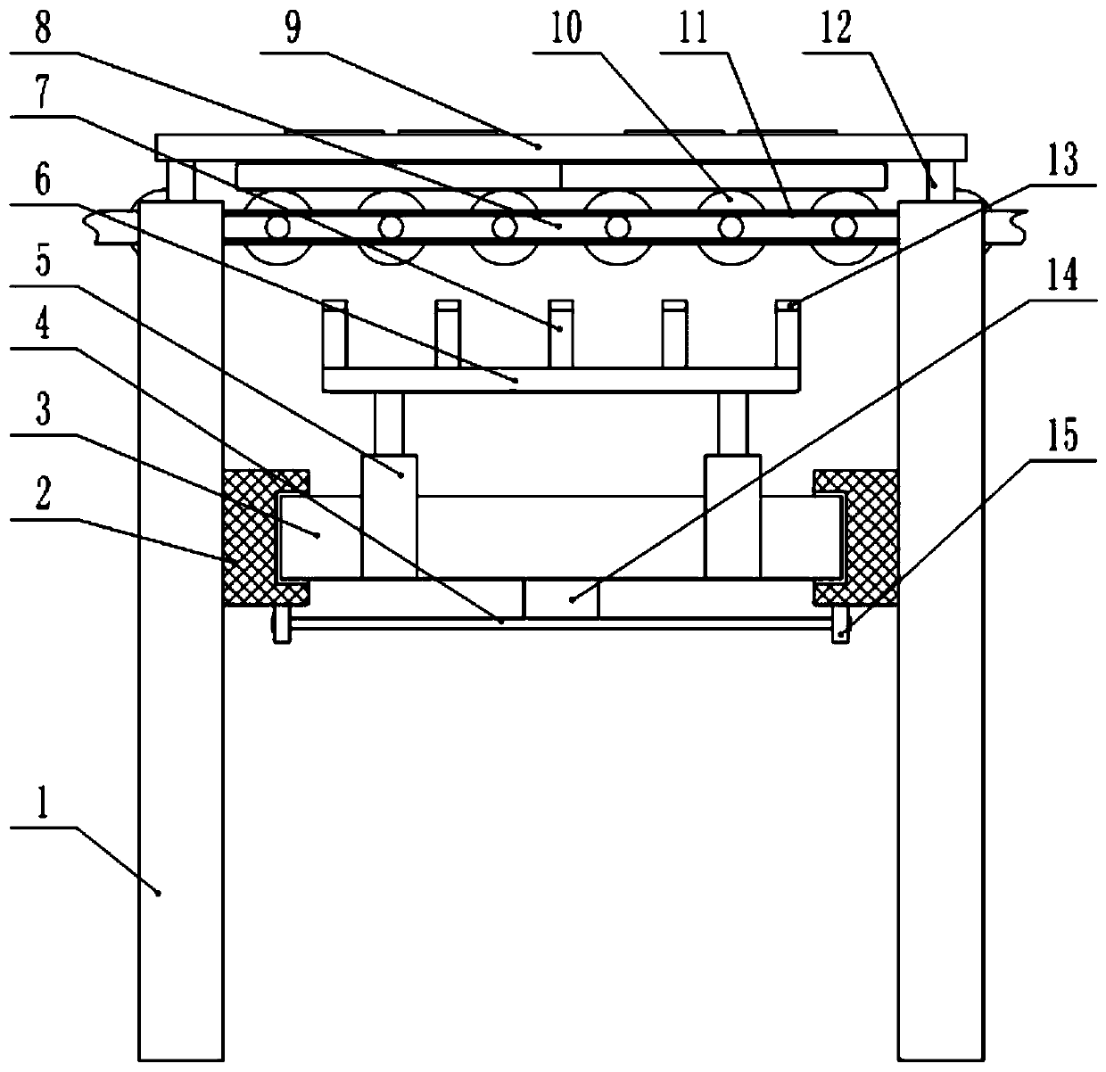
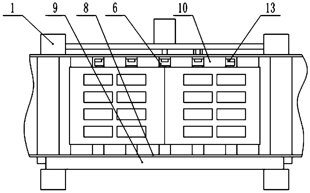
[0023] A stable and efficient plate removal mechanism, comprising a conveying track 8, the conveying track 8 is arranged horizontally, and a plurality of columns 1 corresponding to the left and right are vertically installed on the front and rear sides of the conveying track 8, and the top of the inner wall of the column 1 It is affixed to the outer wall of the conveying track 8, and a plurality of conveying rollers 10 perpendicular to the conveying track 8 are arranged at equal intervals along the conveying direction in the conveying track 8, and the gap between adjacent conveying rollers 10 is smaller than that of the outside world. The thickness of the bricks, the conveying roller 10 is coaxially fixed with a rotating shaft, the front and rear ends of the rotating shaft are rotatably mounted on the front and rear side walls of the conveying track 8, and a transmission belt 11 is connected between the adjacent rotating shafts. , the rear end of one of the rotating shafts is c...
Embodiment 2
[0029]A stable and efficient plate removal mechanism, comprising a conveying track 8, the conveying track 8 is arranged horizontally, and a plurality of columns 1 corresponding to the left and right are vertically installed on the front and rear sides of the conveying track 8, and the top of the inner wall of the column 1 It is affixed to the outer wall of the conveying track 8, and a plurality of conveying rollers 10 perpendicular to the conveying track 8 are arranged at equal intervals along the conveying direction in the conveying track 8, and the gap between adjacent conveying rollers 10 is smaller than that of the outside world. The thickness of the bricks, the conveying roller 10 is coaxially fixed with a rotating shaft, the front and rear ends of the rotating shaft are rotatably mounted on the front and rear side walls of the conveying track 8, and a transmission belt 11 is connected between the adjacent rotating shafts. , the rear end of one of the rotating shafts is co...
Embodiment 3
[0035] A stable and efficient plate removal mechanism, comprising a conveying track 8, the conveying track 8 is arranged horizontally, and a plurality of columns 1 corresponding to the left and right are vertically installed on the front and rear sides of the conveying track 8, and the top of the inner wall of the column 1 It is affixed to the outer wall of the conveying track 8, and a plurality of conveying rollers 10 perpendicular to the conveying track 8 are arranged at equal intervals along the conveying direction in the conveying track 8, and the gap between adjacent conveying rollers 10 is smaller than that of the outside world. The thickness of the bricks, the conveying roller 10 is coaxially fixed with a rotating shaft, the front and rear ends of the rotating shaft are rotatably mounted on the front and rear side walls of the conveying track 8, and a transmission belt 11 is connected between the adjacent rotating shafts. , the rear end of one of the rotating shafts is c...
PUM
 Abstract
Description
Claims
Application Information
 - R&D
- Intellectual Property
- Life Sciences
- Materials
- Tech Scout
- Unparalleled Data Quality
- Higher Quality Content
- 60% Fewer Hallucinations
Browse by: Latest US Patents, China's latest patents, Technical Efficacy Thesaurus, Application Domain, Technology Topic, Popular Technical Reports.
© 2025 PatSnap. All rights reserved.Legal|Privacy policy|Modern Slavery Act Transparency Statement|Sitemap|About US| Contact US: help@patsnap.com


