Supporting device for forming main cable of suspension bridge of space cable system and using method of supporting device

A supporting device and suspension bridge technology, applied in the direction of suspension bridges, bridge forms, bridges, etc., can solve the problems of complex construction, complex space main cable construction, and non-standard temporary fixing devices, and achieve easy disassembly and recycling, good economic benefits, and convenient batch production The effect of chemical production

Pending Publication Date: 2019-10-25
CHANGJIANG SURVEY PLANNING DESIGN & RES
View PDF0 Cites 3 Cited by
  • Summary
  • Abstract
  • Description
  • Claims
  • Application Information

AI Technical Summary

Problems solved by technology

At present, there is no engineering practice of long-span space cable system suspension bridges in China. The main reason is that the construction is complicated, and the construction of space main cables is particularly complicated.
The difference between the space main cable and the planar main cable is that after the main cable is erected, the empty cable naturally sags under the action of its own weight to form a planar main cable, while the space main cable needs to be artificially adjusted and temporarily fixed on the basis of this. The fixing cannot be canceled until all the slings and stiffening beams are installed and a three-dimensional stable system is formed. There is currently no standard for this temporary fixing device

Method used


Image

  • Supporting device for forming main cable of suspension bridge of space cable system and using method of supporting device
  • Supporting device for forming main cable of suspension bridge of space cable system and using method of supporting device
  • Supporting device for forming main cable of suspension bridge of space cable system and using method of supporting device

Examples


Embodiment Construction

[0045] The implementation of the present invention will be described in detail below in conjunction with the accompanying drawings, but they do not constitute a limitation of the present invention, but are only examples; at the same time, the advantages of the present invention will become clearer and easier to understand through description.

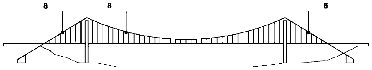
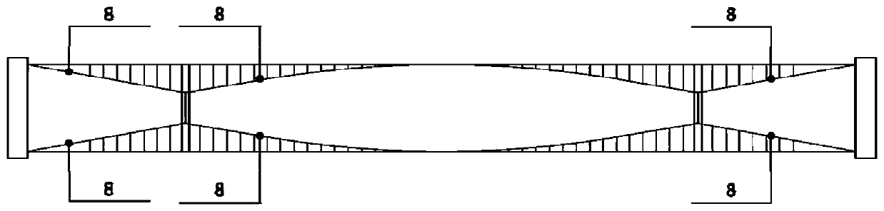
[0046] refer to Figure 1-17 Shown: a supporting device for forming the main cable of a space cable system suspension bridge, which includes a ferrule 1, a short strut 2, a long strut 3, a washer 4, a stopper 5 and a reaction force frame 6;

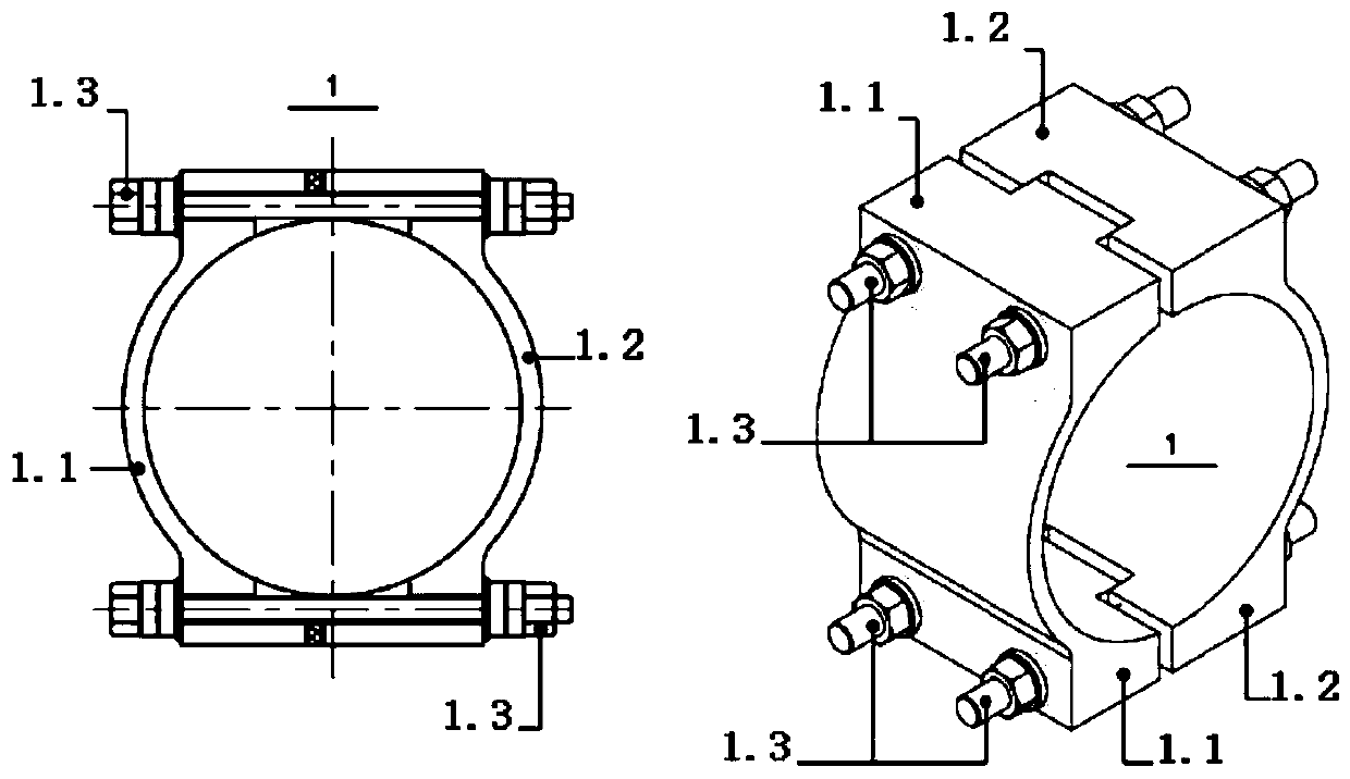
[0047] The two main cables 8 are respectively fixed in the two ferrules 1. The ferrules 1 are composed of two interlocking semi-cylindrical convex tooth ferrules 1.1 and concave tooth ferrules 1.2. The convex tooth ferrule 1.1 and the concave tooth ferrule 1.2 are spliced ​​into a whole through the ferrule bolt 1.3;

[0048] One end of the short strut 2 is fixed on the concave tooth collar 1.2 pro...


PUM


Abstract

The invention discloses a supporting device for forming a main cable of a suspension bridge of a space cable system and a using method of the supporting device. The supporting device comprises sleevehoops (1), a short supporting rod (2), a long supporting rod (3), a gasket (4), a stop block (5) and a counter-force frame (6), two main cables (8) are correspondingly fixed in the two sleeve hoops (1), each of the sleeve hoops (1) is composed of a semi-cylindrical convex gear sleeve hoop body (1.1) and a semi-cylindrical concave gear sleeve hoop body (1.2) which are mutually meshed, the convex gear sleeve hoop bodies (1.1) and the concave gear sleeve hoop bodies (1.2) are spliced into wholes through sleeve hoop bolts (1.3), one end of the short supporting rod (2) is fixed to the concave gearsleeve hoop bodies (1.2) which are arranged on one sides, and the other end of the short supporting rod (2) is sleeved with the tail part of the long supporting rod (3). According to the supporting device for forming the main cable of the suspension bridge of the space cable system and the using method of the supporting device, the defect that a temporary fixing device for the main cable of the suspension bridge of the space cable system does not exist in the prior art is overcome, and the technical problem that the suspension bridge of the space cable system undergoes main cable shaping in ancable finish stage is solved.

Description

technical field [0001] The invention relates to the technical field of suspension bridge construction, in particular to a supporting device and a using method for forming a main cable of a space cable system suspension bridge. Background technique [0002] Compared with the conventional planar cable system suspension bridge, the space cable system suspension bridge consists of main cables, suspension cables and stiffening beams to form a three-dimensional cable system, which greatly improves the transverse stiffness and torsional stiffness of the bridge, and has better dynamic characteristics. Certain advantages. At present, there is no engineering practice of long-span space cable system suspension bridge in China. The main reason is that the construction is complicated, and the construction of the space main cable is particularly complicated. The difference between the space main cable and the planar main cable is that after the main cable is erected, the empty cable natu...

Claims


Application Information

Patent Timeline
Patent Type & Authority Applications(China)
IPC IPC(8): E01D21/00E01D11/02
CPCE01D11/02E01D21/00
Inventor 田卿闫海青周涛赵胤儒李世平唐清华谢三鸿尹邦武何俊荣朱璨
Owner CHANGJIANG SURVEY PLANNING DESIGN & RES
Why Eureka
Try Eureka