Underground hydraulic pump

A technology of hydraulic pumps and jackets, applied in the field of downhole hydraulic pumps, can solve the problems of long operation time, high risk, high operation cost, etc., and achieve the effect of fast speed and convenient lifting and lowering

Pending Publication Date: 2019-10-25
FUXIN CITY GASOLINEEUM TOOL FACTORY
View PDF0 Cites 1 Cited by
  • Summary
  • Abstract
  • Description
  • Claims
  • Application Information

AI Technical Summary

Problems solved by technology

[0002] At present, there are two methods for the hydraulic drop-off packer running in the well at home and abroad. One is the tubing delivery seal method. Seal the hands, and then pull out the oil pipe an

Method used


Image

  • Underground hydraulic pump
  • Underground hydraulic pump

Examples


Example Embodiment

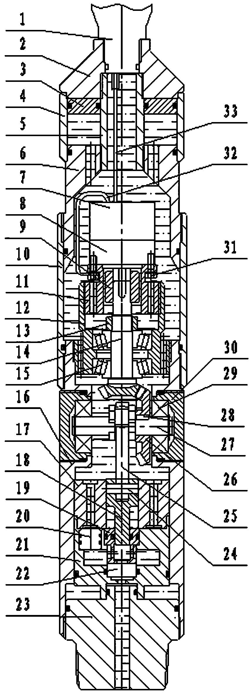
[0012] A downhole hydraulic pump, comprising a tap 1, an upper joint 2, an oil cylinder 4, a central pipe 5, a connecting sleeve 6, an upper outer sleeve 10, an upper inner sleeve 11, a lower inner sleeve 12, a small bevel gear shaft 14, a lower outer sleeve 16, The plunger jacket 17, the tee 21, the lower joint 23, the large bevel gear 26, the gear shaft 27, and the bearing end cover 30 are characterized in that:

[0013] The upper end of the center hole of the upper joint 2 is inserted and threaded with a horse tap 1, the lower end is inserted and threaded with a center pipe 5, the lower end of the center pipe 5 is sleeved and threaded with a connecting sleeve 6, and an oil cylinder is installed between the connecting sleeve 6 and the upper joint 2 4. Oil cylinder 4 is set on the outside of central tube 5 . A piston 3 is installed between the upper joint 2, the connecting sleeve 6, the oil cylinder 4 and the center pipe 5. The piston 3 is sleeved on the central tube 5 . Th...


PUM


Abstract

The invention discloses an underground hydraulic pump. The upper end of an upper connector center hole is inserted in a bridle, and the lower end of the upper connector center hole is inserted into acenter pipe. An oil cylinder is installed between the connecting sleeve and an upper connector. A piston is arranged on the center pipe in a sleeving manner. The upper end of an upper outer sleeve isarranged at the lower end of the connecting sleeve in a sleeving manner, and the lower end of the upper outer sleeve is inserted in a lower outer sleeve. The upper end of the lower outer sleeve is provided with a lower inner sleeve. The upper end of the lower inner sleeve is provided with an upper inner sleeve. A small bevel gear shaft is fixedly installed in inner rings of two first bearings, andthe small bevel gear shaft is sleeved with a nut. The upper end of the upper inner sleeve is in bolt connection with a planetary gearbox and a motor, and the outer side of the lower outer sleeve is in threaded connection with a bearing end cover. A second bearing, a gear shaft, a large bevel gear and a crank are arranged, and a bevel gear transmission mechanism is composed of the large bevel gearand the small bevel gear shaft. A plunger outer sleeve and a tee joint are installed in the lower outer sleeve, and the lower end of the lower outer sleeve is in threaded connection with a lower connector. The lower end of the underground hydraulic pump is connected with a hydraulic releasing type packer, the hydraulic releasing type packer can be screwed off conveniently, the speed is high, andno use risk exists.

Description

technical field [0001] The invention belongs to the technical field of oilfield downhole tools, in particular to a downhole hydraulic pump. Background technique [0002] At present, there are two methods for the hydraulic drop-off packer running in the well at home and abroad. One is the tubing delivery seal method. Seal the hands, and then pull out the oil pipe and the pipe string. This method takes a long time and has high operating costs; the other method uses gunpowder to send the seal. This method has high risks and requires the use of gunpowder. qualifications. Contents of the invention [0003] The purpose of the present invention is to provide a downhole hydraulic pump, the lower end of which is connected to a hydraulic hand-off packer, which is sent into the well by a cable connection, and the ground is used to control the downhole hydraulic pump through the cable transmission power supply. At the same time, the pressure data of the downhole hydraulic pump is tra...

Claims


Application Information

Patent Timeline
IPC IPC(8): E21B23/06E21B23/08
CPCE21B23/06E21B23/08
Inventor 朱玉军刘春雨张光恒
Owner FUXIN CITY GASOLINEEUM TOOL FACTORY
Why Eureka
Try Eureka