Friction structure, friction part and compressor

A technology of friction parts and surface texture, which is applied in the field of compressors, can solve the problems of unable to maintain the fluid lubrication state of the end face, the surface does not have dynamic pressure lubrication characteristics, coating damage and damage, etc.

A technology of friction parts and surface texture, which is applied in the field of compressors, can solve the problems of unable to maintain the fluid lubrication state of the end face, the surface does not have dynamic pressure lubrication characteristics, coating damage and damage, etc.

CN110374881AInactive Publication Date: 2019-10-25ZHUHAI GREE REFRIGERATION TECH CENT OF ENERGY SAVING & ENVIRONMENTAL PROTECTION

Image

  • Friction structure, friction part and compressor
  • Friction structure, friction part and compressor
  • Friction structure, friction part and compressor

Examples


Embodiment Construction

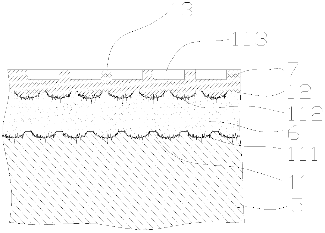
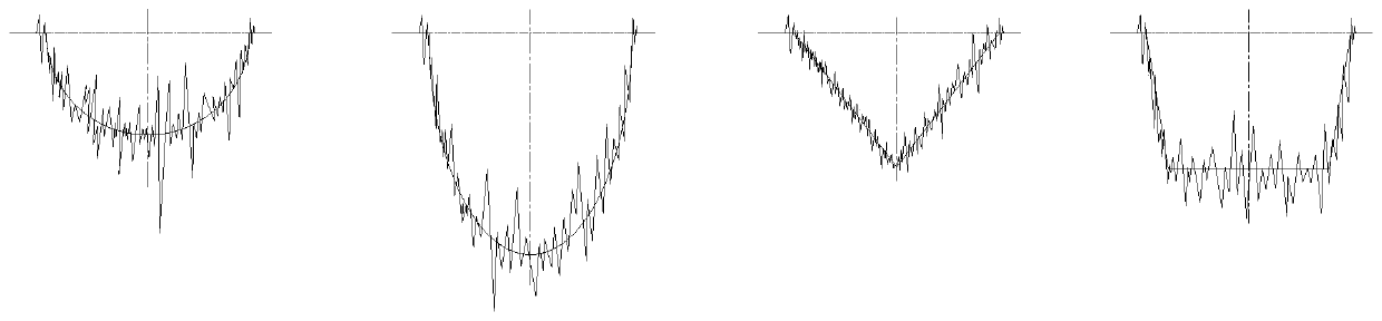
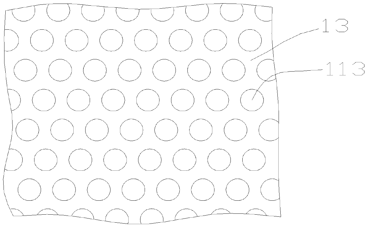
[0034] see in conjunction Figure 1 to Figure 4 As shown, according to an embodiment of the present invention, a friction structure includes a substrate 5 and multiple layers of coatings sequentially bonded on the substrate 5; the first contact surface between the substrate 5 and the adjacent coatings , the second contact surface between two adjacent coatings and the outer surface of the outermost coating are all set as surface texture structures.

[0035] By setting the bonding surface of the substrate 5 and the coating, the bonding surface of two adjacent coatings, and the outer surface of the outermost coating, all the surface texture structures are set. The bonding strength of adjacent parts in the friction structure is increased, and the phenomenon of coating peeling is not easy to occur, and the surface texture structure can be used to achieve dynamic pressure lubrication characteristics, so that the outer surface has a lower friction coefficient and maintains the fluid ...


PUM


Abstract

The invention provides a friction structure, a friction part and a compressor. The friction structure comprises a base and multiple coatings combined on the base in sequence. A first contact face between the base and the adjacent coating, a second contact face between the two adjacent coatings and the outer surface of the coating on the outermost layer are arranged to be of surface texture structures. The base, the coating and the two adjacent coatings combined with the outer surface are arranged to be of the surface texture structures, the binding force is high, lubrication is stable, and abnormal wear is reduced.

Description

technical field [0001] The invention belongs to the technical field of compressors, and in particular relates to a friction structure, friction parts and a compressor. Background technique [0002] The surfaces of pump body parts, such as rollers, flanges, vanes, crankshafts, etc. in rotary compressors, and the surfaces of dynamic and static scrolls, bearings, and cross sliders in scroll compressors, often suffer from abrasive particles, adhesion, Fatigue and other wear forms seriously attenuate the performance of the compressor, which in turn affects its long life and reliability requirements. [0003] In order to solve the problem of friction and wear, the mainstream methods commonly used at present are surface coating treatment and surface texture technology: after coating treatment, the surface hardness and lubricating performance of parts are greatly improved, with better wear resistance and lower wear resistance. The thermal conductivity can significantly improve the ...

Claims


Application Information

Patent Timeline
25 Oct 2019
Publication
CN110374881A
IPC
F04C29/00; F04C29/02
CPC
F04C29/00; F04C29/02; F04C2230/92; F04C2230/91; F04C2240/20; F04C2240/10; F04C2240/80
Inventors
丁少鹏; 刘鹏飞