
Air pressure disc-type brake sliding force simulation test machine

A disc brake and simulation test technology, applied in the testing of machine/structural components, testing of mechanical components, force/torque/power measuring instruments, etc., can solve problems such as inconsistent specifications, inconsistent product weights, and inability to test data

Pending Publication Date: 2019-10-25
SHANDONG TOGET BRAKE SYST CO LTD +1
View PDF0 Cites 2 Cited by
  • Summary
  • Abstract
  • Description
  • Claims
  • Application Information

AI Technical Summary

Problems solved by technology

[0002] At present, there is no special equipment for testing the sliding force of pneumatic disc brakes. Instead, manual testing is used, as long as it can slide freely under the action of its own weight. However, there are disadvantages that the product weight is inconsistent and the specifications are not uniform, so it is impossible to test specific data. , it is impossible to intuitively judge whether the product is qualified through the data

Method used


Image

  • Air pressure disc-type brake sliding force simulation test machine
  • Air pressure disc-type brake sliding force simulation test machine
  • Air pressure disc-type brake sliding force simulation test machine

Examples


Embodiment Construction

[0036] The principles and features of the present invention are described below in conjunction with the accompanying drawings, and the examples given are only used to explain the present invention, and are not intended to limit the scope of the present invention.

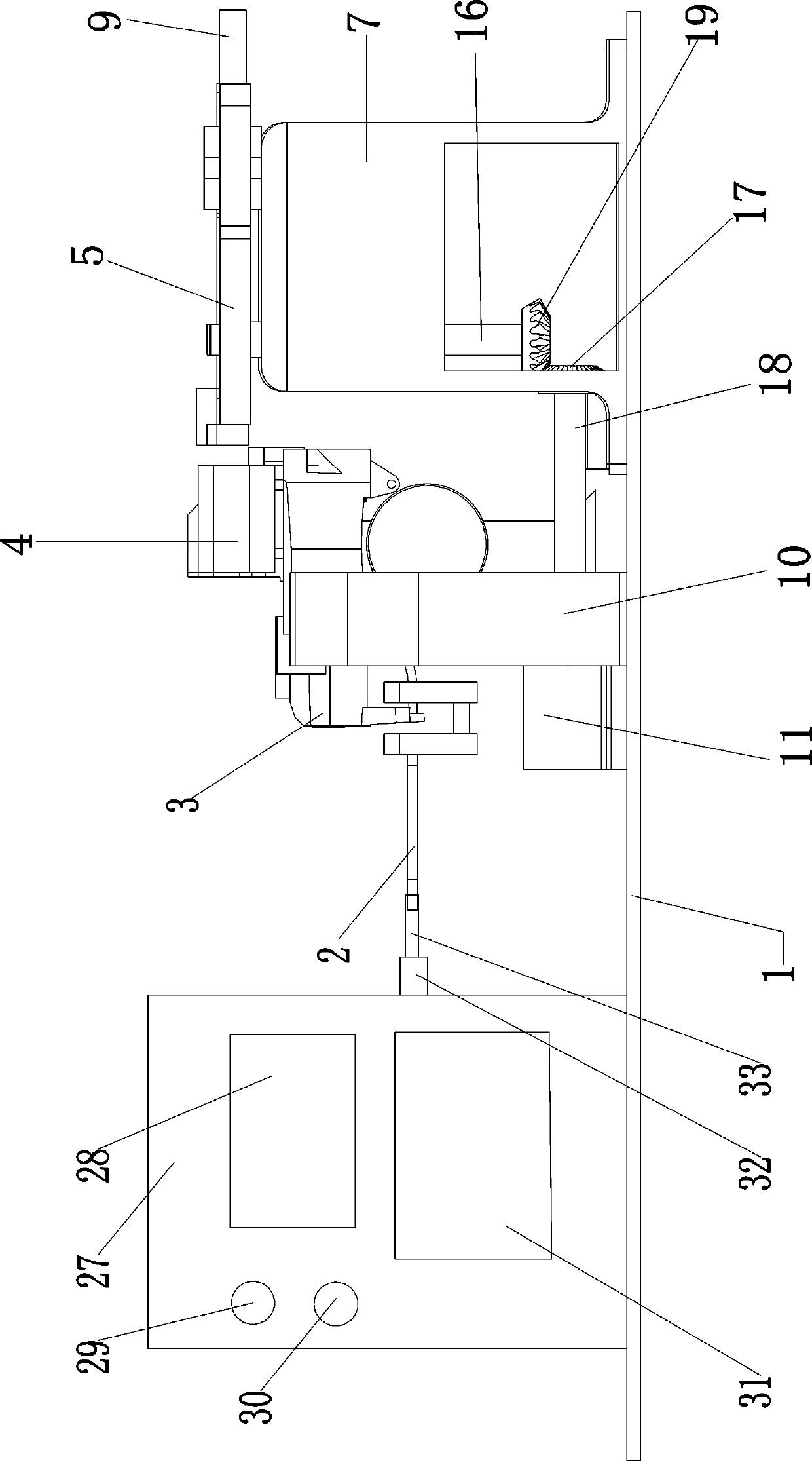
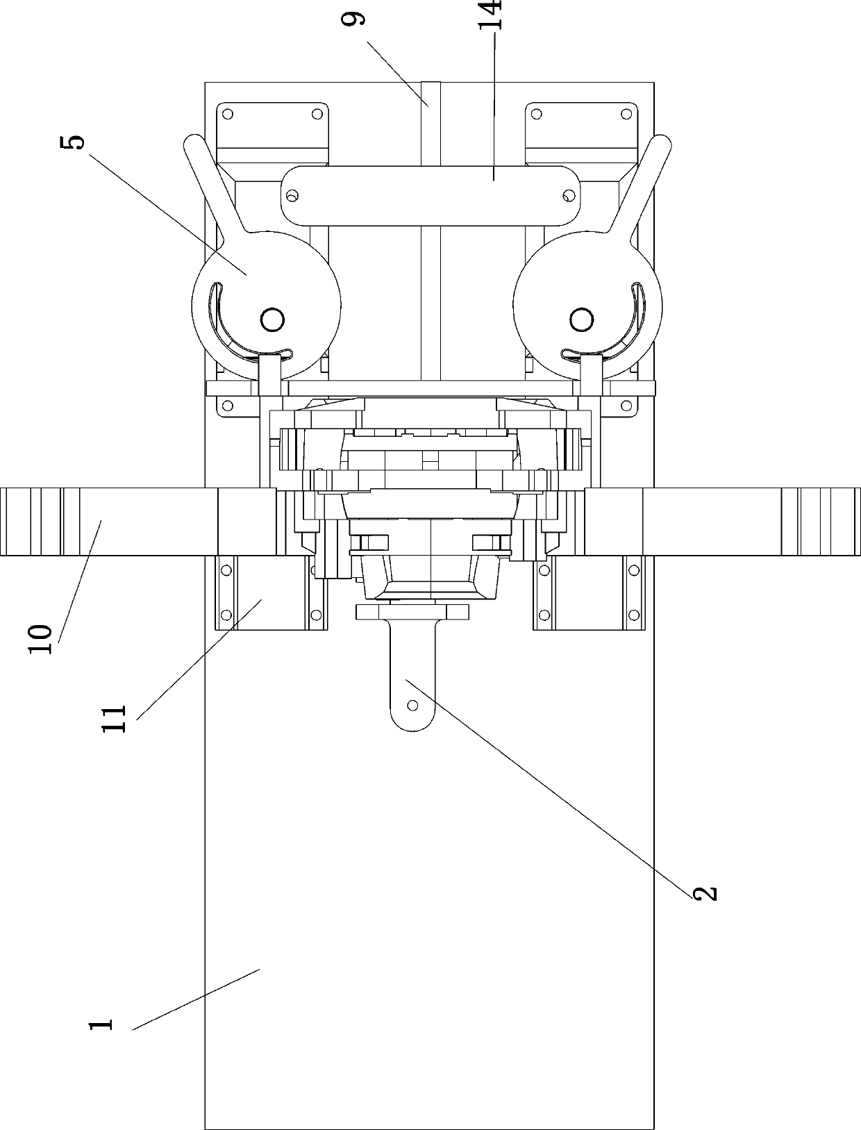
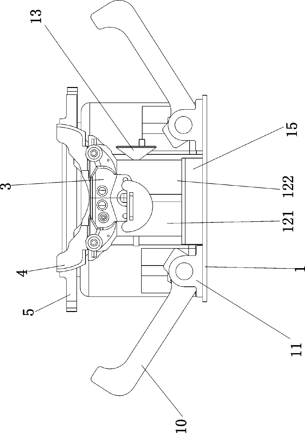
[0037] Such as Figure 1 to Figure 15As shown in the figure, a pneumatic disc brake sliding force simulation testing machine includes a test bench (1), on which a fixed block (15), a cam base (7) and a positioning arm base are fixedly installed (11), the fixed block (15) and the positioning arm base (11) are located on the side of the cam base (7); the cam base (7) is rotatably connected with the eccentric cam (5), and the eccentric cam (5) is provided with There is an arc-shaped arc groove (24), and the center of circle of the arc groove (24) does not coincide with the rotation center of the eccentric cam (5); a positioning push plate (6) is movably connected on the left and right sides of the test bench (1), and t...


PUM


Abstract

An air pressure disc-type brake sliding force simulation test machine comprises a fixed block and a positioning arm pedestal, wherein the fixed block and the positioning arm pedestal are arranged on one side of a cam pedestal; the cam pedestal is rotatably connected with an eccentric cam, an arc-shaped circular arc groove is formed in the eccentric cam, and a circle center of the circular arc groove and a rotating center of the eccentric cam do not coincide; a positioning push plate is connected to an experimental platform in a left-right moving manner, the positioning push plate is arranged on the side of the positioning arm pedestal and the fixed block, a sliding pin is fixedly connected on the positioning push plate, the sliding pin is in transmission connection with the interior of thecircular arc groove, and the eccentric cam is in transmission connection with the positioning push plate; positioning arms arranged in a front-back corresponding mode and capable of fixing a tested clamp body are rotatably connected on the positioning arm pedestal, the free end of each positioning arm extends above the fixed block, and the positioning arms are in transmission connection with theeccentric cam; and a bracket supporting base used for accommodating a tested bracket is connected to the fixed block, the bracket supporting base is positioned on one side of the positioning push plate, the positioning push plate is pushed toward the tested bracket after the eccentric cam rotates, meanwhile, the positioning arms rotate inwardly to clamp the tested clamp body tightly.

Description

technical field [0001] The invention relates to a testing device, in particular to a testing machine for simulating and testing the sliding force of a pneumatic disc brake. Background technique [0002] At present, there is no special equipment for testing the sliding force of pneumatic disc brakes. Instead, manual testing is used, as long as it can slide freely under the action of its own weight. However, there are disadvantages that the product weight is inconsistent and the specifications are not uniform, so it is impossible to test specific data. , It is impossible to intuitively judge whether the product is qualified through the data. Contents of the invention [0003] Aiming at the shortcomings, the present invention provides a pneumatic disc brake slip force simulation testing machine, which adopts automatic operation, which reduces the labor intensity and difficulty of workers, and the machine also adopts an intelligent detection system, which reduces the probabili...

Claims


Application Information

Patent Timeline
Patent Type & Authority Applications(China)
IPC IPC(8): G01M13/00G01L5/28
CPCG01M13/00G01L5/28
Inventor 朱润涛许崇海张炳荣衣明东张中国杨传亮邓文兴裴志浩冯成斌
Owner SHANDONG TOGET BRAKE SYST CO LTD
Learn More