A multi-base cooperative radio detection system and detection method

A radio detection and multi-base technology, applied in the field of radio detection, to ensure time synchronization, improve distance accuracy, and improve the effect of multi-pulse accumulation

Active Publication Date: 2021-06-29
BEIJING CHANGFENG BROADCASTING COMM EQUIP
View PDF8 Cites 0 Cited by
  • Summary
  • Abstract
  • Description
  • Claims
  • Application Information

AI Technical Summary

Problems solved by technology

[0004] The embodiment of the present invention provides a multi-base cooperative radio detection system and detection method, which can solve the time synchronization problem of each base station, thereby improving the detection and positioning accuracy, and improving the cumulative efficiency of the system

Method used


Image

  • A multi-base cooperative radio detection system and detection method
  • A multi-base cooperative radio detection system and detection method
  • A multi-base cooperative radio detection system and detection method

Examples


Embodiment 1

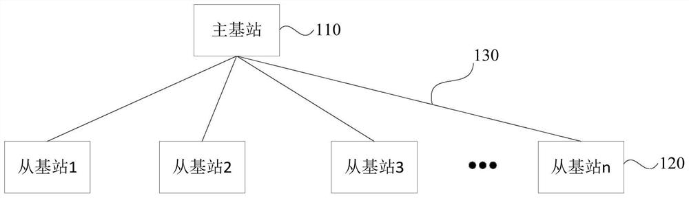
[0033] figure 1 It is a schematic structural diagram of a multi-base cooperative radio detection system provided by Embodiment 1 of the present invention. The system is used to implement the multi-base cooperative radio detection method described in the embodiment of the present invention. Such as figure 1 As shown, the system includes:

[0034] At least one master base station 110 and at least three slave base stations 120 , the master base station 110 and the slave base stations 120 are connected through an Ethernet 130 .

[0035] The master base station 110 is used to transmit frequency modulation step signals, and send communication data to the slave base station 120 through the Ethernet 130, and receive the detection information sent by the slave base station 120, and determine the detection target based on the detection information using a time difference positioning method location information, wherein the communication data includes a first clock signal.

[0036] T...

Embodiment 2

[0079] Figure 14 It is a flowchart of a multi-base cooperative radio detection method provided by Embodiment 2 of the present invention. The method is executed by a multibase cooperative radio detection system, and system synchronization can be realized by executing the method. Such as Figure 14 As shown, the method includes:

[0080] Step 110, the master base station transmits a frequency modulation step signal, and sends communication data to the slave base station through the Ethernet.

[0081] In the embodiment of the present invention, the communication data includes the first clock signal. At least one master base station and at least three slave base stations are connected through Ethernet to form a multi-base cooperative radio detection system.

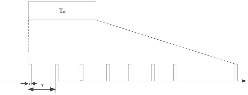
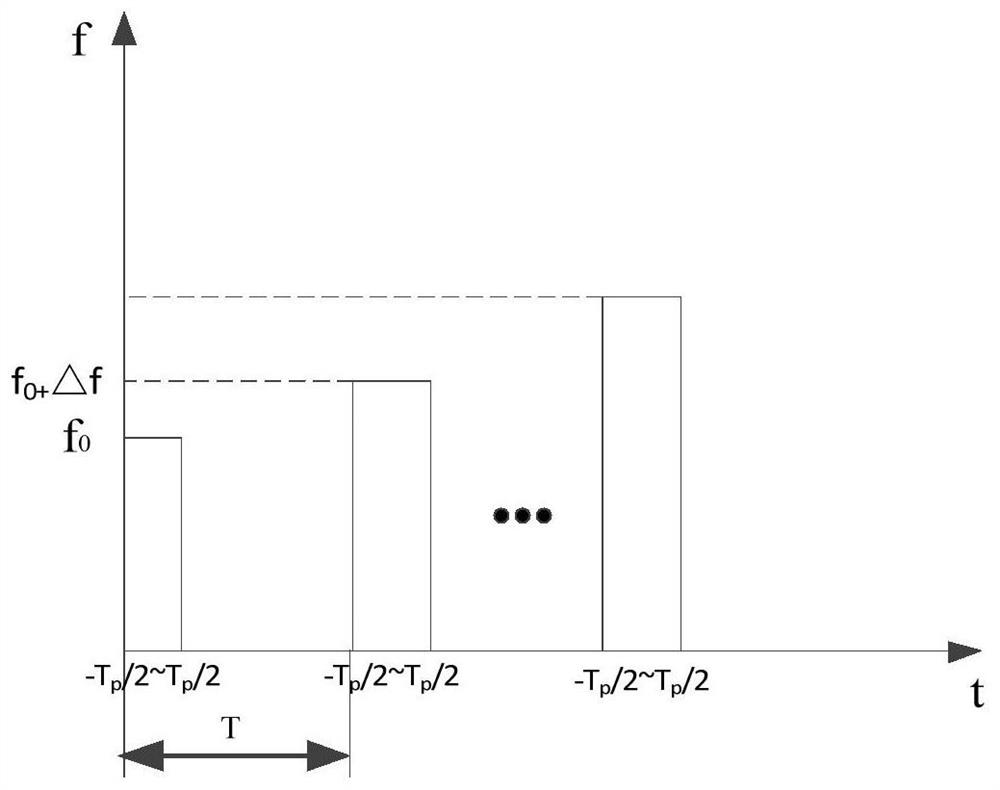
[0082] It should be noted that the pulse width of the FM step signal is determined according to the expected detection blind zone, the FM bandwidth and the number of pulses of the FM step signal are determined according ...


PUM


Abstract

The invention discloses a multi-base cooperative radio detection system and a detection method. The system transmits FM step signal and communication data to the slave base station through the master base station. Obtain the first clock signal from the communication data from the base station, adjust the local clock signal according to the first clock signal to obtain the second clock signal, determine the first receiving time of the frequency modulation step signal transmitted by the main base station based on the second clock signal, and detect The second receiving time of the reflected FM stepping signal reflected by the target; the first receiving time and the second receiving time are used as detection information, and are sent to the main base station through the Ethernet. The main base station uses the time difference positioning method to determine the location information of the detection target based on the detection information, ensuring the time synchronization of the radio detection devices at multiple points, thereby improving the distance accuracy; improving the multi-pulse accumulation effect of the radio detection devices at multiple base stations, thereby improving detection distance capability.

Description

technical field [0001] Embodiments of the present invention relate to radio detection technology, in particular to a multi-base cooperative radio detection system and detection method. Background technique [0002] The radio detection method is an effective non-cooperative target detection method, and the three-coordinate safety control and regional alert control of the target area can be realized through the radio detection method. [0003] Radio detection means include single-base mode and multi-base mode. Wherein, the monostatic mode may be a radar detection mode. However, since the radar transmits signals at the transmitting end, the receiving end cannot receive the signals, resulting in a large coverage blind area in the single-base mode radio detection method. The radio detection means in the multi-base mode can easily solve the problem of coverage blind spots, but how to synchronize the radio detection devices in multiple places is still an urgent problem to be solv...

Claims


Application Information

Patent Timeline
Patent Type & Authority Patents(China)
IPC IPC(8): G01S13/06
CPCG01S13/06
Inventor 李艳东王志宇刘巍付浩然杨颖蔡晓葳王荷竹段东辉张明芮缪苗高建超姚少峰姜泽飞况学伟刘旺史晓雄高锐达
Owner BEIJING CHANGFENG BROADCASTING COMM EQUIP
Why Eureka
Try Eureka