Three-input majority logic device based on TFET

A majority logic, three-input technology, applied in the direction of semiconductor devices, electrical components, circuits, etc., to achieve the effect of saving quantity, reducing circuit area, and small area

Active Publication Date: 2019-10-25
NINGBO UNIV
View PDF4 Cites 1 Cited by
  • Summary
  • Abstract
  • Description
  • Claims
  • Application Information

AI Technical Summary

Problems solved by technology

However, these devices are still in their infancy, limited to theoretica...

Method used


Image

  • Three-input majority logic device based on TFET
  • Three-input majority logic device based on TFET
  • Three-input majority logic device based on TFET

Examples


Embodiment 1

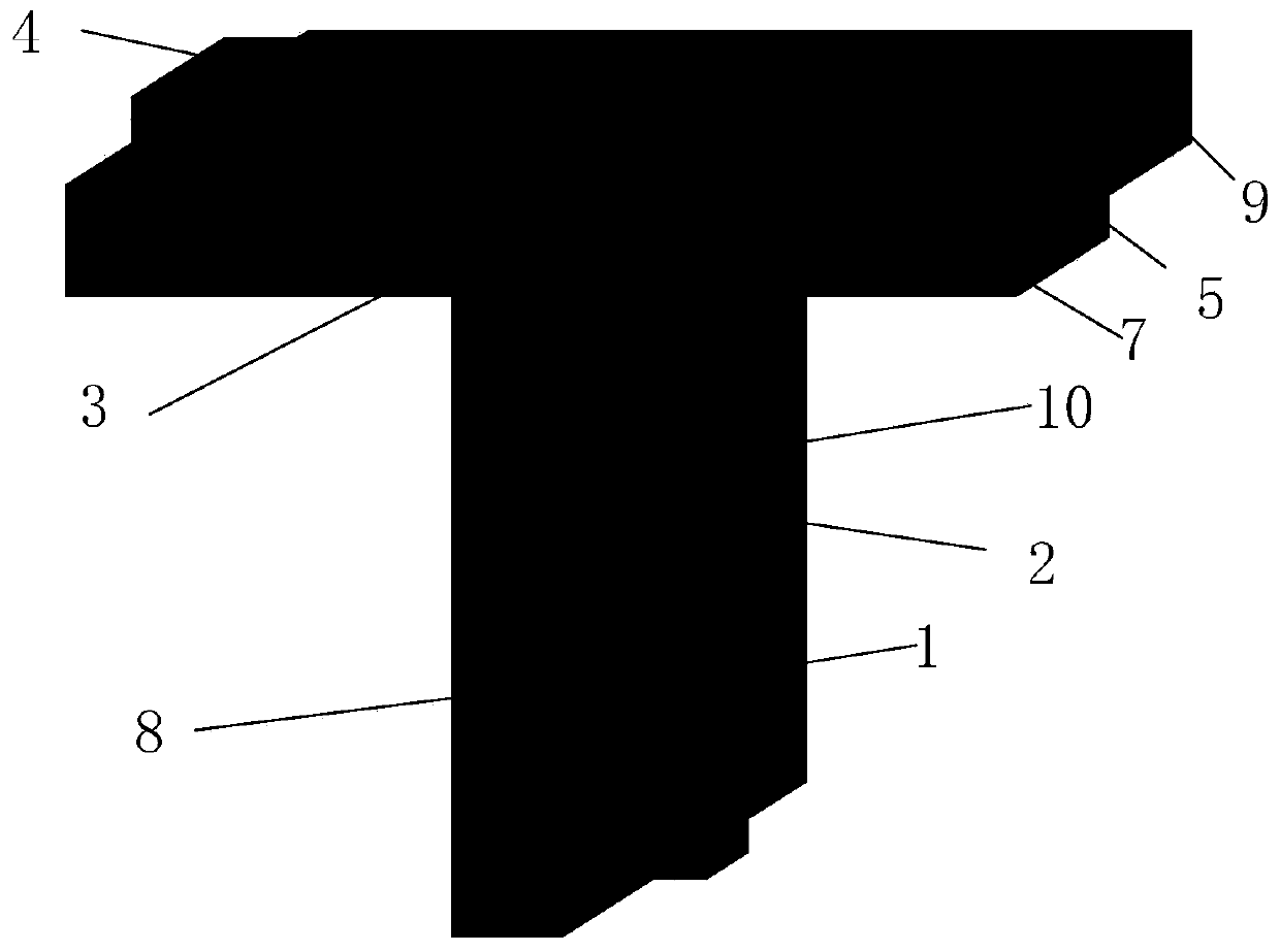
[0018] Embodiment 1: As shown in the figure, a TFET-based three-input majority logic device includes a channel region, a source region, a drain region, a first gate oxide layer, a second gate oxide layer 1, a third gate The oxide layer 2, the first metal gate, the second metal gate 3 and the third metal gate 4; the channel region is a T-shaped structure composed of the first rectangular block 5 and the second rectangular block 6, the first rectangular block 5 is arranged horizontally, the second rectangular block 6 is vertically arranged, the second rectangular block 6 is perpendicular to the first rectangular block 5, the upper end surface of the second rectangular block 6 is connected with the lower end surface of the first rectangular block 5, and the first rectangular block The front end face of the block 5 and the front end face of the second rectangular block 6 are located in the same plane, the rear end face of the first rectangular block 5 and the rear end face of the s...

Embodiment 2

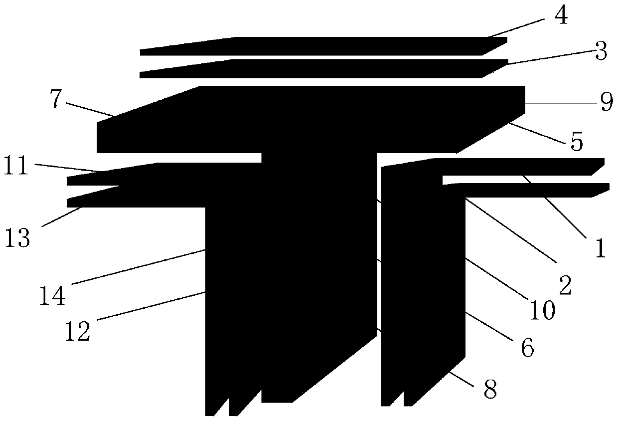
[0021]Embodiment 2: As shown in the figure, a TFET-based three-input majority logic device includes a channel region, a source region, a drain region, a first gate oxide layer, a second gate oxide layer 1, and a third gate The oxide layer 2, the first metal gate, the second metal gate 3 and the third metal gate 4; the channel region is a T-shaped structure composed of the first rectangular block 5 and the second rectangular block 6, the first rectangular block 5 is arranged horizontally, the second rectangular block 6 is vertically arranged, the second rectangular block 6 is perpendicular to the first rectangular block 5, the upper end surface of the second rectangular block 6 is connected with the lower end surface of the first rectangular block 5, and the first rectangular block The front end face of the block 5 and the front end face of the second rectangular block 6 are located in the same plane, the rear end face of the first rectangular block 5 and the rear end face of th...


PUM

PropertyMeasurementUnit
Doping concentrationaaaaaaaaaa
Work functionaaaaaaaaaa
Lengthaaaaaaaaaa

Abstract

The invention discloses a three-input majority logic device based on a TFET. The three-input majority logic device comprises a channel region, a source region, a drain region, a first gate oxide layer, a second gate oxide layer, a third gate oxide layer, a first metal gate electrode, a second metal gate electrode and a third metal gate electrode, wherein the channel region is of a T-shaped structure composed of a first rectangular block and a second rectangular block, and the source region is of a T-shaped structure composed of a third rectangular block and a fourth rectangular block. The drain region is of a T-shaped structure composed of a fifth rectangular block and a sixth rectangular block. The structure of the second gate oxide layer and the structure of the first gate oxide layer are bilaterally symmetrical relative to the center line of the second rectangular block in the vertical direction, and the structure of the second metal gate electrode and the structure of the first metal gate electrode are bilaterally symmetrical relative to the center line of the second rectangular block in the vertical direction; the third gate oxide layer is arranged on the upper end surface ofthe first rectangular block, and the third metal gate electrode is arranged on the upper end surface of the third gate oxide layer. The device has the advantages of compact structure, small area and low power consumption.

Description

technical field [0001] The invention relates to a three-input majority logic device, in particular to a TFET-based three-input majority logic device. Background technique [0002] In digital logic circuits, a three-input Majority-Logic (MAJ) device is the most basic logic device. Three-input majority logic devices combined with inverters can implement all Boolean functions. Since three-input majority logic devices have multi-input characteristics and can accept and generate more electrical information, in digital logic gate-level circuits, three-input majority logic devices can be used as a basic general-purpose logic unit for building complex circuits. At present, the three-input majority logic device has been widely used in the carry module of the full adder unit circuit. [0003] Existing three-input majority logic devices are usually implemented by CMOS technology, and the implementation methods are generally static complementary structure, transmission gate structure ...

Claims


Application Information

Patent Timeline
IPC IPC(8): H01L29/739H01L29/10H01L29/08H01L29/423
CPCH01L29/7391H01L29/1037H01L29/0847H01L29/42364H01L29/42356
Inventor 胡建平叶浩
Owner NINGBO UNIV
Why Eureka
Try Eureka