Multifunctional interface communication terminal for distribution network

A technology of multi-function interface and communication terminal, applied in the field of multi-function interface communication terminal of distribution network, can solve problems such as hindering the smooth progress of communication, incompatible communication protocols, and inability to interconnect, and achieve effective identification and encrypted transmission, and on-site installation. The method is simple and quick, and the effect of improving data security and reliability

Active Publication Date: 2019-10-25
STATE GRID SHANDONG ELECTRIC POWER CO YANTAI CITY FUSHAN DISTRICT POWER SUPPLY CO
View PDF6 Cites 0 Cited by
  • Summary
  • Abstract
  • Description
  • Claims
  • Application Information

AI Technical Summary

Problems solved by technology

[0004] The purpose of the present invention is to solve the problem in the prior art that the communication protocols are incompatible with each other and cannot be interconnected with each other, which hinders the smooth progress of communication. At the same time, during the u

Method used


Image

  • Multifunctional interface communication terminal for distribution network
  • Multifunctional interface communication terminal for distribution network
  • Multifunctional interface communication terminal for distribution network

Examples


Embodiment 1

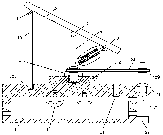
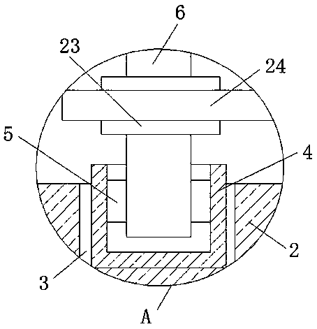
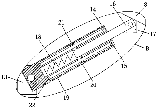
[0027] refer to Figure 1-6 , distribution network multifunctional interface communication terminal, including a communication terminal body 1 set as a hollow structure, a fixed plate 2 is fixedly installed on the top of the communication terminal body 1, and a placement groove 3 is opened on the top of the fixing plate 2, and the placement groove 3 is fixed and installed There is a placement block 4, the top of the placement block 4 is provided with a rotating groove 5, and a rotating column 6 is installed in the rotating groove 5, and the top of the rotating column 6 extends to the top of the placing block 4 and a roller 7 is installed on the top of the roller 7. The signal receiving board 8 arranged obliquely is fixedly installed, and the bottom of the signal receiving board 8 is fixedly installed with a first rotating seat 9, and a moving rod 10 is installed rotating on the first rotating seat 9, and an annular groove 11 is opened on the top of the communication terminal bo...

Embodiment 2

[0036] refer to Figure 1-6 , distribution network multi-function interface communication terminal, including a communication terminal body 1 set as a hollow structure, the top of the communication terminal body 1 is fixedly connected with a fixing plate 2 by bolts, the top of the fixing plate 2 is provided with a placement slot 3, and the placement slot 3 The placement block 4 is fixedly connected by bolts, the top of the placement block 4 is provided with a rotating groove 5, and a rotating column 6 is installed in the rotating groove 5, and the top of the rotating column 6 extends to the top of the placing block 4 and a roller 7 is installed in rotation. The top of the roller 7 is fixedly connected with an inclined signal receiving plate 8 by bolts, and the bottom of the signal receiving plate 8 is fixedly connected with a first rotating seat 9 by bolts, and a moving rod 10 is mounted on the first rotating seat 9 for rotation, and the communication terminal body The top of ...


PUM


Abstract

The invention belongs to the field of communication terminals, in particular relates to a multifunctional interface communication terminal for a distribution network, and provides the following schemeaiming at the problems that the existing communication protocols are incompatible, cannot be interconnected and hinders smooth communication, and meanwhile, a signal receiving plate does not have anangle adjusting function in the use process so that the signal is poor. The communication terminal comprises a communication terminal body with a hollow structure, wherein a fixed plate is fixedly mounted at the top of the communication terminal body; and a placing groove is formed in the top of the fixing plate. The communication terminal is simple in structure, convenient to operate, high in device integration, small in size and simple, convenient and rapid in on-site installation method, and the on-site transformation cost of the distribution network is greatly reduced; and the signal receiving plate can be rotated and subjected to angle adjustment at the same time, the signal receiving plate is adjusted to a place with strong signals, and received signals are enhanced, so the requirements of people are met.

Description

technical field [0001] The invention relates to the technical field of communication terminals, in particular to a distribution network multi-function interface communication terminal. Background technique [0002] The distribution automation system is an integrated system for remote real-time monitoring, coordination and control of the equipment on the distribution network. The distribution network terminal is one of the important basic equipment of the smart grid. In view of the risk of network attacks, power distribution automation needs to use reliable communication methods to upload various information collected by the terminal equipment on the power distribution site to the monitoring center, and at the same time send the data from the monitoring center to the on-site terminal equipment. Distribution network terminal equipment is currently unable to meet the stability and safety and reliability requirements of distribution network automation line data transmission. If ...

Claims


Application Information

Patent Timeline
IPC IPC(8): H04Q1/02
CPCH04Q1/028H04Q1/035
Inventor 刘抗抗吴枫王永强孙友军赵琳杨晓婧胡红程培强周蕾孙海峰韩孟良徐菲菲魏昺淇吕尚谕宇阳
Owner STATE GRID SHANDONG ELECTRIC POWER CO YANTAI CITY FUSHAN DISTRICT POWER SUPPLY CO
Why Eureka
Try Eureka